Hexapod System | Stewart Platform | 6-Axis Correction
- Hexapod = Stewart platform: 6 telescopic struts connecting 2 rings = 6 DOF
- Reference ring: Fixed ring (usually proximal) defines coordinate system
- Moving ring: Ring that moves relative to reference ring during correction
- Mounting parameters: 14 measurements (7 per ring) required for software
- Total residual: Combined measure of all deformity components - correction complete when approaches zero
- “Stewart platform originally designed for flight simulators (1965)
- “TSF can correct all 6 axes simultaneously - unlike Ilizarov
- “Virtual hinge at CORA minimises unwanted translation during angular correction
- “Frame mounting errors cause residual deformity - precision critical
Overview and Principles
The Taylor Spatial Frame (TSF) is a hexapod external fixator, developed by Dr J. Charles Taylor in Memphis, Tennessee. Two rings are joined by six telescopic struts, and graduated strut adjustments, calculated by computer-assisted planning, correct a deformity in all six axes simultaneously.
The Stewart platform. The mechanism is the Stewart-Gough platform, described by D. Stewart in 1965 for flight simulation: six linear actuators connecting two platforms give six degrees of freedom. The same kinematic mechanism is used in flight simulators, robotic surgery and precision positioning systems, and Taylor applied it to orthopaedic external fixation in the 1990s.
Six degrees of freedom. Three are translational and three rotational:
- Translational - anterior-posterior, medial-lateral, and axial (shortening or lengthening)
- Rotational - varus/valgus (coronal angulation), flexion/extension or recurvatum/procurvatum (sagittal angulation), and axial rotation (torsion)
Against the Ilizarov. The hexapod corrects every axis at once, where an Ilizarov frame needs sequential corrections. Its hinge is virtual, calculated by the software, so no physical hinge is placed and the same construct stays on throughout treatment; a deformity that persists is simply re-prescribed, and computer-assisted planning reduces human calculation errors. The price is cost, in struts and software.
- Taylor Spatial Frame (TSF)
- 6 telescopic struts (hexapod)
- Ilizarov Circular Fixator
- Rods, hinges, motors (modular)
- Taylor Spatial Frame (TSF)
- 6 DOF simultaneous correction
- Ilizarov Circular Fixator
- Sequential corrections required
- Taylor Spatial Frame (TSF)
- Computer software (web-based)
- Ilizarov Circular Fixator
- Mechanical/manual planning
- Taylor Spatial Frame (TSF)
- Virtual hinge (software)
- Ilizarov Circular Fixator
- Physical hinges required
- Taylor Spatial Frame (TSF)
- Not required during treatment
- Ilizarov Circular Fixator
- Often needed for direction changes
- Taylor Spatial Frame (TSF)
- Software-dependent (steep initially)
- Ilizarov Circular Fixator
- Traditional mechanics (steep)
- Taylor Spatial Frame (TSF)
- Higher (struts, software)
- Ilizarov Circular Fixator
- Lower (traditional components)
- Taylor Spatial Frame (TSF)
- Easy re-prescription via software
- Ilizarov Circular Fixator
- Frame reconfiguration needed
Indications and Contraindications
Indications. The frame is used across four groups of problem:
- Deformity correction - complex multiplanar deformity (congenital, developmental or post-traumatic), tibial and femoral malunion, deformity from rickets or Blount disease, and angular deformity with rotational and translational components
- Limb lengthening - limb length discrepancy requiring distraction osteogenesis, lengthening combined with deformity correction, congenital short femur and fibular hemimelia
- Fracture management - acute fracture reduction with gradual correction, malunion correction with osteotomy, and nonunion with deformity
- Infection and bone loss - bone transport for segmental defects, infected nonunion, and use combined with the Masquelet technique
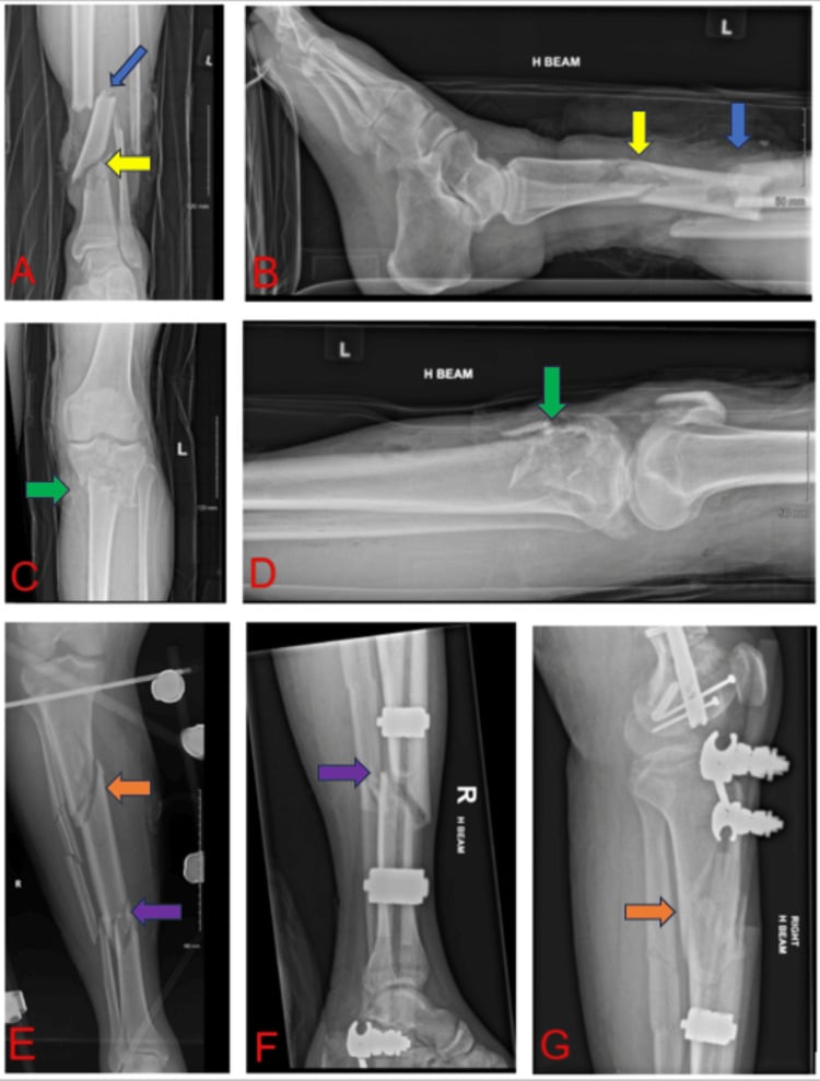
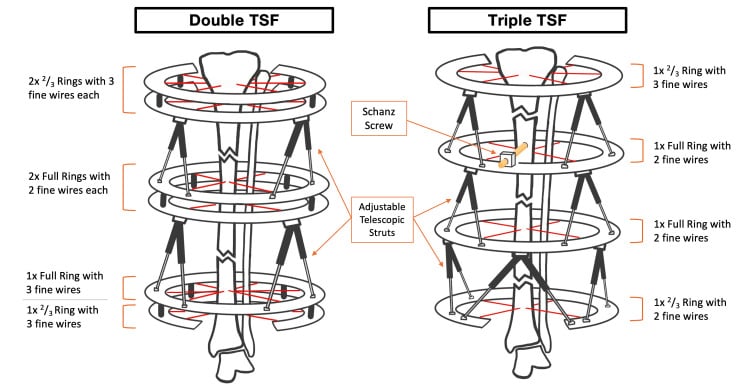
Stacked frames. A multisegmental fracture with separate fracture levels needs independently controlled segments. Double- and triple-stacked TSF constructs place one independently adjustable hexapod across each principal fracture line, with intermediate rings sharing fixation between adjacent segments.
Contraindications. The absolute contraindications are:
- Active systemic sepsis
- Soft-tissue compromise severe enough to preclude pin or wire placement
- A non-compliant patient, unable to perform the daily adjustments
- Inadequate bone stock for wire or pin fixation
The relative contraindications are:
- Severe peripheral vascular disease
- Uncontrolled diabetes mellitus
- Osteoporosis, which may require a modified technique
- Morbid obesity, because of concerns about frame stability
- Psychological unsuitability
Technical Principles
Inverse kinematics. The software is given the desired end position and orientation of the moving ring and calculates the strut lengths required to reach it. That is inverse kinematics; forward kinematics is the opposite, calculating position from joint angles.
The construct. Every TSF is built from the same parts:
- Two rings, the reference ring and the moving ring
- Six telescopic struts, threaded for length adjustment
- Universal joints at each end of every strut, allowing multi-axis rotation at the strut-ring connections
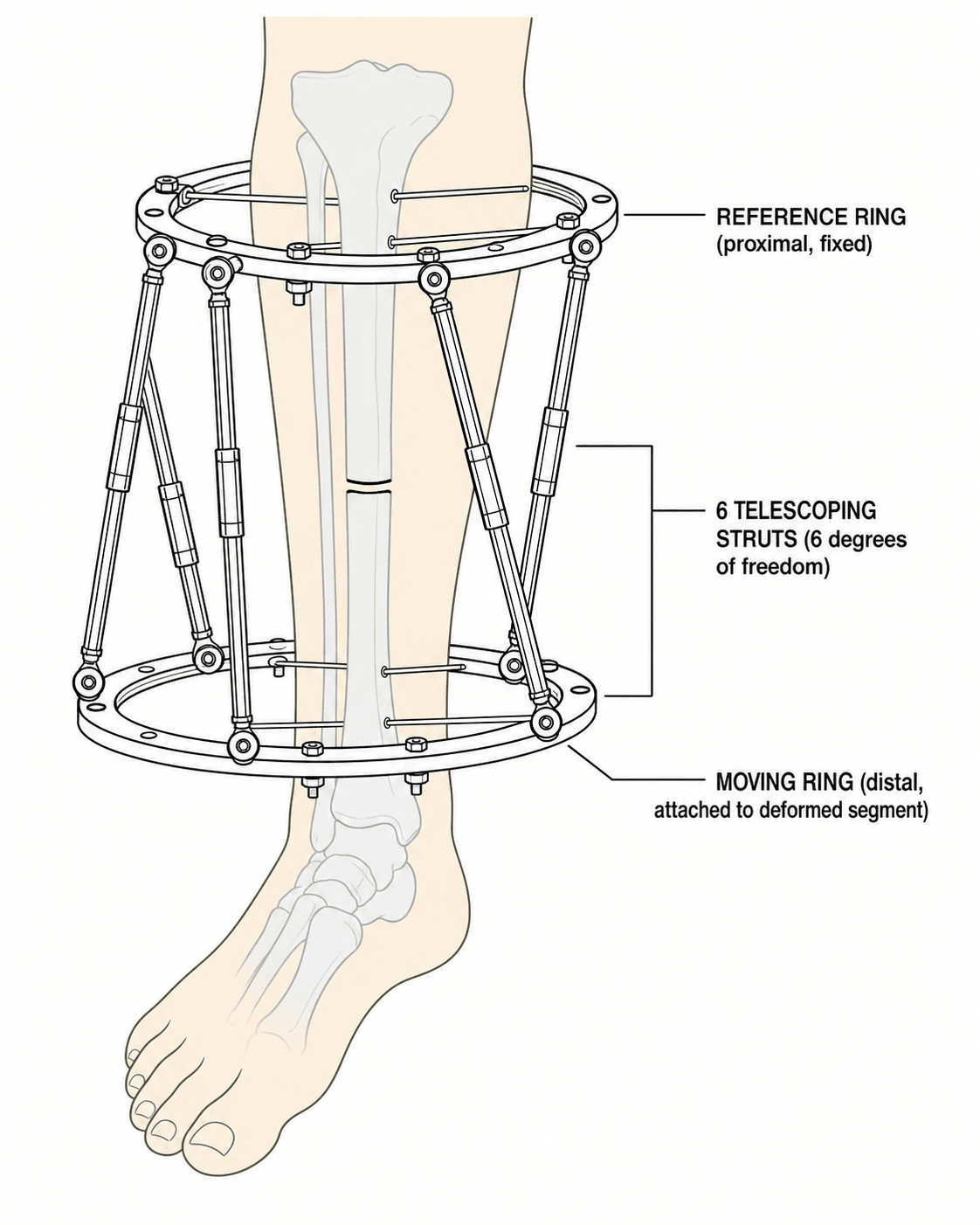
Why six struts. Six struts give exactly six degrees of freedom, the minimum required for full spatial positioning. It is the mathematical equivalent of six linear equations with six unknowns: a fully determined system, neither over- nor under-constrained.
Reference and moving rings. The reference ring is the "fixed" ring that defines the coordinate system, and every deformity parameter is measured relative to it. It is usually placed on the proximal (stable) segment, by convention the ring closest to the trunk. The moving ring is attached to the distal (deformed) segment and moves to the corrected position as the struts adjust.
The choice of reference ring affects how deformity is prescribed to the software. If you select the proximal ring as reference, describe the deformity of the distal segment. Be consistent - errors in reference ring selection lead to correction in the wrong direction.
The virtual hinge. The centre of rotation of angulation (CORA) is the intersection of the proximal and distal mechanical axes and the ideal pivot for angular correction. Correction about the CORA produces pure angulation without translation; correction about a point away from it produces combined angulation and translation. An Ilizarov frame gets pure angulation from physical hinges placed at the CORA. The TSF software instead calculates strut adjustments that simulate rotation about a hinge at any specified point, so a virtual hinge at the CORA minimises secondary translation, and it can be repositioned during treatment if needed.
Total residual. The total residual is a composite measure of the deformity remaining across all six axes, calculated by the software once the current deformity parameters are entered. It combines the angular (degrees) and translational (mm) components into a single weighted value that approaches zero as correction completes. It is used to monitor progress, to set the endpoint (typically less than 5 mm equivalent) and to identify incomplete corrections that need adjustment.
Surgical Technique
Imaging. Long-leg standing AP and lateral radiographs, a CT scan to assess rotational deformity, and EOS imaging if available, which gives a full-length image at low radiation.
Deformity analysis. The analysis records:
- Mechanical axis deviation (MAD), the distance from the mechanical axis to the joint centre
- The CORA, which may be single or multiple
- The angular deformity: magnitude, direction, and plane (coronal, sagittal or oblique)
- Translational deformity
- Rotational deformity, which requires CT
- Limb length discrepancy
If the CORA lies outside the bone, plan for a secondary correction. A lengthening is planned around a corticotomy.
Rings. Choose a diameter that leaves 2-3 fingerbreadths of clearance all round and allows for soft-tissue swelling; larger rings give better access but reduce stability. The configuration is chosen from full rings, 5/8 rings and foot plates. In the proximal tibia consider knee range of motion, in the distal tibia ankle clearance, and in the femur half-rings may be needed for sitting.
Assembly. In order:
- Assemble the rings with appropriate connectors
- Attach the six struts to their designated mounting positions
- Ensure the universal joints move freely
- Check that the strut length range is adequate for the planned correction
- Record the strut positions on the mounting worksheet
Wires and pins. Each ring needs a minimum of two fixation elements, wires and/or pins, placed through safe corridors that avoid the neurovascular structures. Tensioned wires of 1.5-1.8 mm provide ring stability and half-pins of 5-6 mm add to it. Olive wires are tensioned to 130-150 kg and smooth wires to 110-130 kg, and all are re-tensioned after 48 hours as they settle.
Tibial corridors. For the proximal ring the safe wire runs from the fibular head to the posteromedial tibia, avoiding the peroneal nerve, with a reference wire perpendicular to the tibial axis. For the distal ring the safe zone is anterior to posterior, protecting the anterior tibial vessels.
Software Planning: Mounting Parameters and the Prescription
Mounting parameters. The software has to know where the frame sits on the bone, and it needs 14 mounting parameters, 7 per ring, to do so:
- Ring internal diameter, in mm
- Ring-to-ring distance between the reference and moving rings
- AP frame offset from the bone axis (anterior positive, posterior negative)
- Lateral (ML) frame offset from the bone axis (medial positive, lateral negative)
- Rotational orientation, given by the position of the master tab (anterior, lateral, posterior or medial)
- Strut positions, the numbered mounting holes for each strut
- Segment and side: proximal or distal, left or right
They are measured on standardised AP and lateral radiographs and recorded on the mounting parameter worksheet. The offsets are the hard part, and have a section of their own below.
Origin and corresponding point. The surgeon chooses an origin, a defined reference point on the reference (fixed) fragment, conventionally at the osteotomy level on the reference-ring side. The corresponding point is the matching point on the moving fragment, the one that should end up superimposed on the origin once the deformity is corrected. The deformity is then described as the translations and angulations needed to move the corresponding point onto the origin.
What the software computes. It takes two sets of inputs: the mounting parameters, which describe the frame at rest, and the deformity parameters, which are the AP and lateral angulation, the AP, lateral and axial translation, and the axial rotation of the corresponding point relative to the origin. Together these give the current position of the rings relative to each other and the desired final position, and from them the software computes the six daily strut lengths. Placing the origin at the CORA puts the virtual hinge there; an origin away from the CORA is still resolved by the software, but the translation it adds must be intended.
Deformity modes. The software works in three modes:
- Chronic mode - gradual correction of an established deformity
- Residual mode - adjustment when the initial correction is incomplete. The surgeon re-defines the current corresponding-point offset (the residual program) and the software issues a fresh strut schedule, with no frame rebuild, unlike an Ilizarov
- Total residual mode - monitoring the combined deformity
The strut schedule. The output is a daily length change for each of the six struts, scheduled over the correction period, typically weeks to months. The rate can be made faster or slower, and the duration depends on the magnitude of the deformity.
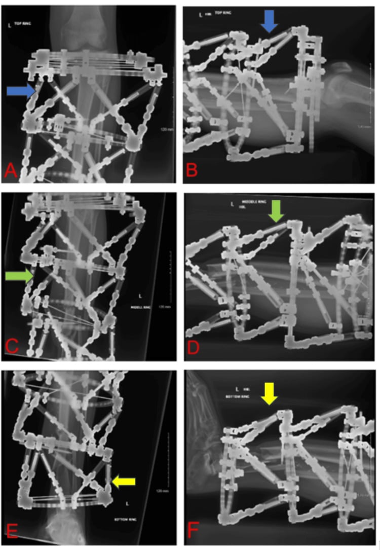
Stacked frames. Each hexapod segment of a stacked construct must be imaged perpendicular to its own reference ring, so the software receives valid deformity and mounting measurements.
Frame Offset: the Dominant Source of Residual Deformity
What the offset is. The frame offset is the perpendicular distance from the bone (reference) axis to the centre of the reference ring, in the AP and lateral planes. Together with ring diameter and ring-to-ring distance it locates the ring in space relative to the bone, so the software knows where the frame is.
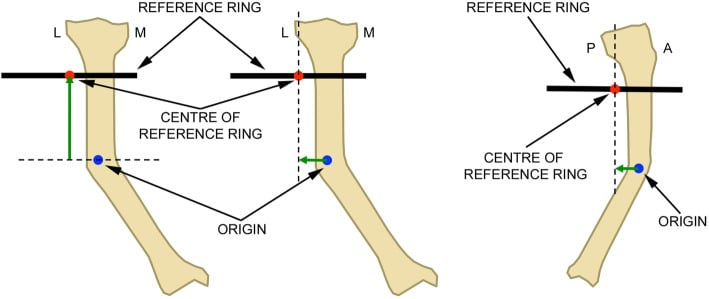
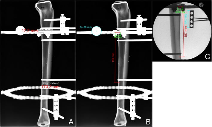
Why it dominates the error budget. Offset is the hardest parameter to measure and the most error-prone, and the measurement gets less accurate the further the origin sits from the reference ring (Gessmann, in the evidence cards). The software has been told the bone axis is somewhere it is not, so the error reappears at the end of correction as a residual translation of essentially the same magnitude, plus an angular error of arctan(offset error / ring-to-ring distance).
The "1 mm per degree" rule. The often-quoted 1 mm of offset error per degree of residual angulation is that formula evaluated at a ring-to-ring distance of about 57 mm. It holds for a short construct, and the angular error is roughly half that at 100 mm and a third at 150 mm. Take the message (small offset errors matter, and matter more the shorter the construct) rather than the number.
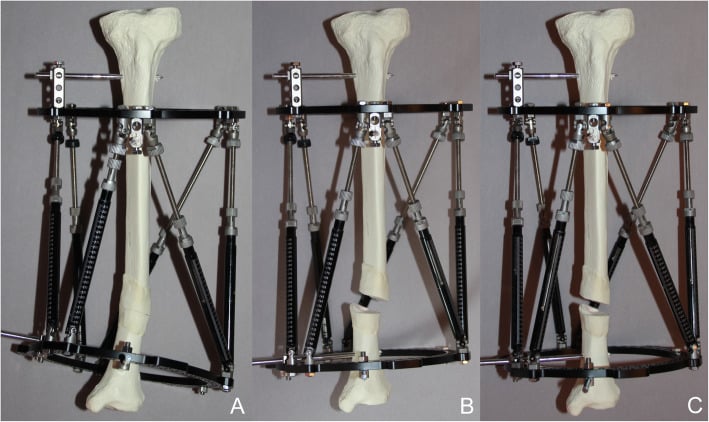
Measuring it. Draw the bone axis on true AP and lateral films and measure the perpendicular distance to the ring centre. Use calibrated radiographs (a calibration marker of known size) or a calibrated image intensifier; non-calibrated films are the least accurate.
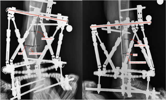
The CT alternative. Basing the correction on the actual 3D frame-to-bone position on CT compensates for mounting error more completely: in phantoms, residual error was less than 2 degrees of rotation and less than 0.5 mm of length. Because of cost and radiation it is reserved for complex cases, and routine CT planning is not universally adopted.
Complications
Pin-site infection. This is the most common complication by a wide margin, and near-universal over a multi-month correction. Reported incidence spans 11.3 to 100 percent across series, a range so wide it mostly reflects differing definitions and surveillance rather than differing practice, so any incidence figure must be quoted with caution. The great majority are minor: around 94 percent respond to local care or oral antibiotics in one large paediatric series, and roughly three-quarters are graded minor when the Checketts-Otterburn system is applied. Staphylococcus aureus is the usual organism, followed by Pseudomonas aeruginosa.
Checketts-Otterburn grading. The minor/major split is the whole point of the classification. Grades 1-3 are managed with the frame in place; grades 4-6 mean the external fixation must be abandoned.
- Findings
- Slight redness, little discharge
- Treatment
- Improved pin-site care
- Findings
- Redness, discharge, pain and soft-tissue tenderness
- Treatment
- Pin care plus oral antibiotics
- Findings
- As grade 2 but no improvement on oral antibiotics
- Treatment
- Affected pin(s) RESITED - external fixation continues
- Findings
- Severe soft-tissue infection involving several pins, often with pin loosening
- Treatment
- External fixation must be abandoned
- Findings
- As grade 4 with radiographic changes
- Treatment
- External fixation must be abandoned
- Findings
- Infection after fixator removal: track heals then breaks down and discharges intermittently; new bone or sequestra on radiographs
- Treatment
- Curettage of the pin track
Grade 4 and above belong in theatre for formal debridement of the tracks, not on the ward with a longer antibiotic course.
Pin loosening. Loosening presents as pain, instability and increased discharge. The common teaching that it follows infection is the wrong way round as often as not: loosening is frequently the initiating event, motion at the bone-pin interface breaking the seal and infection following. That makes prevention a mechanical problem (construct stability, atraumatic insertion, no skin tension) rather than an antiseptic one.
Insertion technique. This is where it is won:
- Pre-drill, even self-drilling half-pins
- Drill in a pulsed fashion with cold saline irrigation, to avoid thermal necrosis
- Irrigate the pilot hole to clear bone swarf
- Avoid the thick anterior tibial crest
- Stretch any muscle compartment that must be traversed, so the pins do not transfix it shortened
Hydroxyapatite-coated half-pins. They hold better than uncoated pins: extraction torque exceeds insertion torque, the reverse of uncoated pins, with markedly less osteolysis and loosening. That is worth the cost in a frame expected to stay on for months.
Resite rather than simply remove. Taking a pin out without replacing it destabilises the construct and transfers load to the remaining pins, which then loosen in turn.
Frame instability. Pin failure, ring breakage or strut malfunction can leave the frame unstable, which requires urgent assessment and revision.
Choosing the Correction Method
When a multiplanar deformity is identified, the exam question is usually "which device or technique?" Justify the choice from the clinical features below rather than reaching reflexively for a hexapod.
- Preferred strategy
- Acute osteotomy + plate/monolateral fixator
- Why
- Single plane corrects accurately in one stage; avoids prolonged frame
- Preferred strategy
- Hexapod (TSF) gradual six-axis correction
- Why
- Simultaneous correction of all axes; virtual hinge; software residual mode
- Preferred strategy
- Hexapod or Ilizarov with distraction osteogenesis
- Why
- Gradual distraction needed; hexapod adds 3D angular control
- Preferred strategy
- Osteotomy at CORA (acute or gradual)
- Why
- Pure angular correction without secondary translation
- Preferred strategy
- Ilizarov or hexapod bone transport +/- Masquelet
- Why
- Manages infection, dead space and length together
- Preferred strategy
- Hexapod gradual correction
- Why
- Avoids acute open surgery through poor envelope
- Preferred strategy
- Traditional Ilizarov
- Why
- No per-case software/strut cost; equivalent biology
- Preferred strategy
- Internal/acute correction (avoid gradual frame)
- Why
- Gradual correction fails without reliable strut adjustment
Guidelines, Registries & Global Practice
The TSF (Smith & Nephew) is one of several hexapod systems worldwide; equivalent platforms include the TrueLok-Hex (Orthofix), the Ortho-SUV frame, and the MAXFRAME (Zimmer Biomet). All share Stewart-platform kinematics and web/desktop planning software, so the principles below are device-agnostic.
Global epidemiology and case mix:
- Hexapod frames are concentrated in tertiary limb-reconstruction units because of the planning, monitoring and patient-compliance demands.
- Commonest indications globally: post-traumatic tibial malunion/nonunion, congenital and developmental deformity (Blount disease, rickets, fibular hemimelia, congenital short femur), and limb-length discrepancy.
- In high-burden, limited-resource regions, neglected fractures and infected nonunions (often post-bonesetter) form a disproportionate share of the workload.
Societies, training and standards (side-by-side):
- Role relevant to hexapod frames
- Limb reconstruction courses, deformity-analysis curriculum, outcome reporting standards
- Role relevant to hexapod frames
- Deformity-correction and external-fixation education; CORA / mechanical-axis planning
- Role relevant to hexapod frames
- Open-fracture and external-fixation pin-site care standards applicable to ring/hexapod frames
- Role relevant to hexapod frames
- External fixation and limb-reconstruction educational resources
- Role relevant to hexapod frames
- Fellowship-level deformity-correction training and consensus
There is no single high-level guideline mandating hexapod over Ilizarov; selection is guided by deformity complexity, surgeon experience, software access and cost.
No dedicated hexapod-frame registry equivalent to arthroplasty registries (NJR, AJRR, AOANJRR) exists. Evidence is dominated by single-centre series and systematic reviews; this is a recognised limitation when quoting union and complication rates.
- High-resource: hexapod frame with software planning, CT-based deformity analysis, calibrated imaging for mounting parameters, dedicated physiotherapy and pin-site clinics.
- Limited-resource: traditional Ilizarov constructs remain first-line because of lower cost and no per-case software/strut expense; hexapods reserved for the most complex multiplanar cases.
- Across all settings, success depends on daily strut adjustment compliance and pin-site care over a typical 3-6 month treatment; multidisciplinary input (surgeon, physiotherapist, orthotist) is essential.
Related pages: Hexapod Frame Deformity Correction is the companion page on the same device concept, and carries the Stewart-Gough platform kinematics and the applications survey in more depth; Ilizarov External Fixation is the parent technique this replaced computationally but not biologically - the wire tensioning, ring construction and distraction-osteogenesis biology are unchanged and live there; Deformity Analysis - CORA and MAD is the non-negotiable prerequisite, because a hexapod executes a prescription and cannot rescue a deformity that was analysed wrongly, and the joint-orientation angles and osteotomy rules on that page are what generate the six deformity parameters entered here; Limb Lengthening Principles for latency, rate and rhythm and for the healing index this page's systematic review reports; Distraction Osteogenesis for the regenerate biology that determines how long the frame stays on; Bone Transport Techniques for segmental defects, where the same frame solves a different problem; Blount Disease and Congenital Pseudarthrosis of the Tibia are the paediatric conditions behind much of the carded evidence, and the recurrence-with-growth problem the short follow-up in those series cannot see; Guided Growth for Angular Deformity Correction is the alternative that should be considered first in a child with growth remaining, because a plate and two screws beat six months in a frame whenever the physis will do the work; Malunion and Delayed Union and Nonunion Management for the post-traumatic deformities that are the commonest adult indication; Ankle Arthritis for the joint the supramalleolar osteotomy carded above is trying to preserve; and Limb Length Discrepancy - Epiphysiodesis for the far simpler answer to a modest discrepancy in a growing child.
Controversies & Areas of Uncertainty
Hexapod versus Ilizarov. Hexapods give superior 3D control and easier residual re-prescription, but the comparative data are largely level III-IV single-centre series. Systematic review evidence suggests a potentially higher healing index with hexapods, and no high-level trial proves a union-rate advantage.
Acute versus gradual correction. Gradual six-axis correction is more accurate for complex deformity, yet for a simple uniplanar deformity acute one-stage correction avoids months in a frame. The threshold, often cited around 10 degrees of uniplanar varus, is convention, not high-level evidence.
Latency, rate and rhythm of distraction. The classic latency and rate in the Correction Protocol derive from distraction-osteogenesis biology, but the optimal rate varies with age, site and regenerate quality, and is individualised rather than protocolised.
Pin-site care. Reported infection rates are commonly 30 percent or more, mostly superficial, and no single cleaning regimen is proven superior.
Exam Viva Scenarios
Practise clinical reasoning and management decisions out loud
“Explain the Taylor Spatial Frame to me. How does it work and what advantages does it offer over traditional Ilizarov frames?”
“A 25-year-old man presents with a tibial malunion following conservative treatment of a fracture 2 years ago. Radiographs show 20 degrees varus angulation, 15 degrees procurvatum, and 2cm shortening. How would you plan correction using a TSF?”
“You applied a TSF for correction of a tibial deformity. At the end of the planned correction schedule, radiographs show a 10-degree residual varus deformity. What went wrong and how would you manage this?”
Hexapod Principles
- Stewart platform: 6 struts, 2 rings, 6 DOF
- 3 translational: AP, ML, axial
- 3 rotational: varus/valgus, flexion/extension, rotation
- Virtual hinge at CORA (no physical hinge)
Mounting Parameters (14 total)
- 7 per ring: diameter, ring distance, AP offset, lateral offset
- Master tab position, strut positions, segment/side
- Errors cause residual deformity
- Standardized measurement protocol essential
Reference vs Moving Ring
- Reference ring: stable segment (usually proximal)
- Moving ring: deformed segment (moves during correction)
- Defines coordinate system for software
- Be consistent with ring selection
Software Planning
- Input 14 mounting parameters
- Prescribe deformity in all 6 axes
- Software calculates daily strut changes
- Residual mode for mid-treatment adjustment
TSF vs Ilizarov Advantages
- Simultaneous multiplanar correction
- No hinge placement or frame rebuilding
- Computer-assisted (reduces errors)
- Easy residual correction via software
Distraction Protocol
- Latency: 5-7 days before starting
- Rate: 1mm/day in 4 divided doses
- Angular correction: 1-2 degrees/day
- Total residual approaches zero when complete
Evidence Base
Gradual (six-axis) versus acute correction of tibia vara
- Retrospective comparative study: 18 tibiae gradual TSF correction vs 14 tibiae acute correction
- Accurate angulation correction in 17/18 gradual vs 7/14 acute limbs
- Accurate translation (within 5 mm) in 18/18 gradual vs 7/14 acute
- Residual mechanical axis deviation 3.1 mm (gradual) vs 17.1 mm (acute)
Accuracy of radiographic measurement of TSF mounting parameters
- Sawbone tibia study comparing 150 radiographic mounting-parameter measurements to direct caliper reference
- Non-calibrated radiographs (method A) showed the highest variance vs reference
- Error increased with greater origin-to-reference-ring distance
- Calibrated radiographs and calibrated image-intensifier images were accurate and intercomparable (p=0.226)
Femoral deformity correction with the TSF in children and young adults
- 20 patients (22 limbs), age 5.9-24.6 years; mean time in frame 6.2 months
- Frontal and sagittal plane deformities corrected to within normal values
- Mean lengthening 4.9 cm (range 1.5-9 cm); external fixation index 2.2 months/cm
- 15 complications in 13 limbs (pin-tract infection, knee stiffness, delayed union, posterior knee subluxation)
Supramalleolar osteotomy with six-axis correction for distal tibial deformity
- 52 adults (mean age 44 years); 22 had oblique-plane deformities; mean time in frame 4 months
- All postoperative distal tibial joint-orientation angles within 0-4 degrees of normal
- Mean AOFAS improved from 40 to 71 (p less than 0.001)
- Complications: two osteotomy nonunions; three later required ankle fusion
Computer-assisted distraction osteogenesis: 3D-CT vs radiographic frame mounting
- Method computes correction from the actual frame-to-bone position on 3D CT, immediately compensating for mounting errors
- 20 tibial phantom experiments: mean residual error less than 2 degrees rotation and less than 0.5 mm length
- Pilot clinical study of 5 patients showed clinically acceptable corrections with no complications
- Supports CT-based planning as more accurate than radiograph-derived mounting parameters
Hexapod fixation for lengthening in disproportionate short stature (systematic review)
- 20-year systematic review (2004-2024) of hexapod limb lengthening in short stature
- Mean lengthening 3-5.9 cm; healing index 37-68.6 days/cm
- Most frequent complications: pin-site infection, compartment syndrome, delayed union
- TSF allowed more accurate corrections but often a higher healing index than other external fixators
Prevention and management of external fixator pin track sepsis
- Reported pin-track infection incidence ranges from 11.3 to 100 percent across series
- Checketts-Otterburn grades 1-3 are minor and managed with the frame in situ; grades 4-6 are major and the external fixation must be abandoned
- Pin loosening is frequently the cause rather than the consequence of infection, so construct stability and atraumatic insertion are the primary preventive measures
- Hydroxyapatite-coated pins show extraction torque exceeding insertion torque, with far less osteolysis and loosening than uncoated pins
- Septic pins should be RESITED rather than simply removed, because removal destabilises the construct and loosens the remaining pins