Computed Tomography for Orthopaedic Surgeons
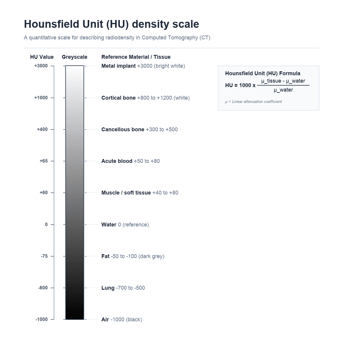
Air: -1000 HU (black)
Fat: -50 to -100 HU (dark grey)
Water: 0 HU (reference grey)
Soft tissue/muscle: +40 to +80 HU (grey)
Cancellous bone: +300 to +500 HU (light grey)
Cortical bone: +800 to +1200 HU (white)
Metal: +3000 HU (bright white with artefact)
Key: The Hounsfield Unit is a linear transformation of the attenuation coefficient normalised to water — this is the fundamental unit of CT imaging
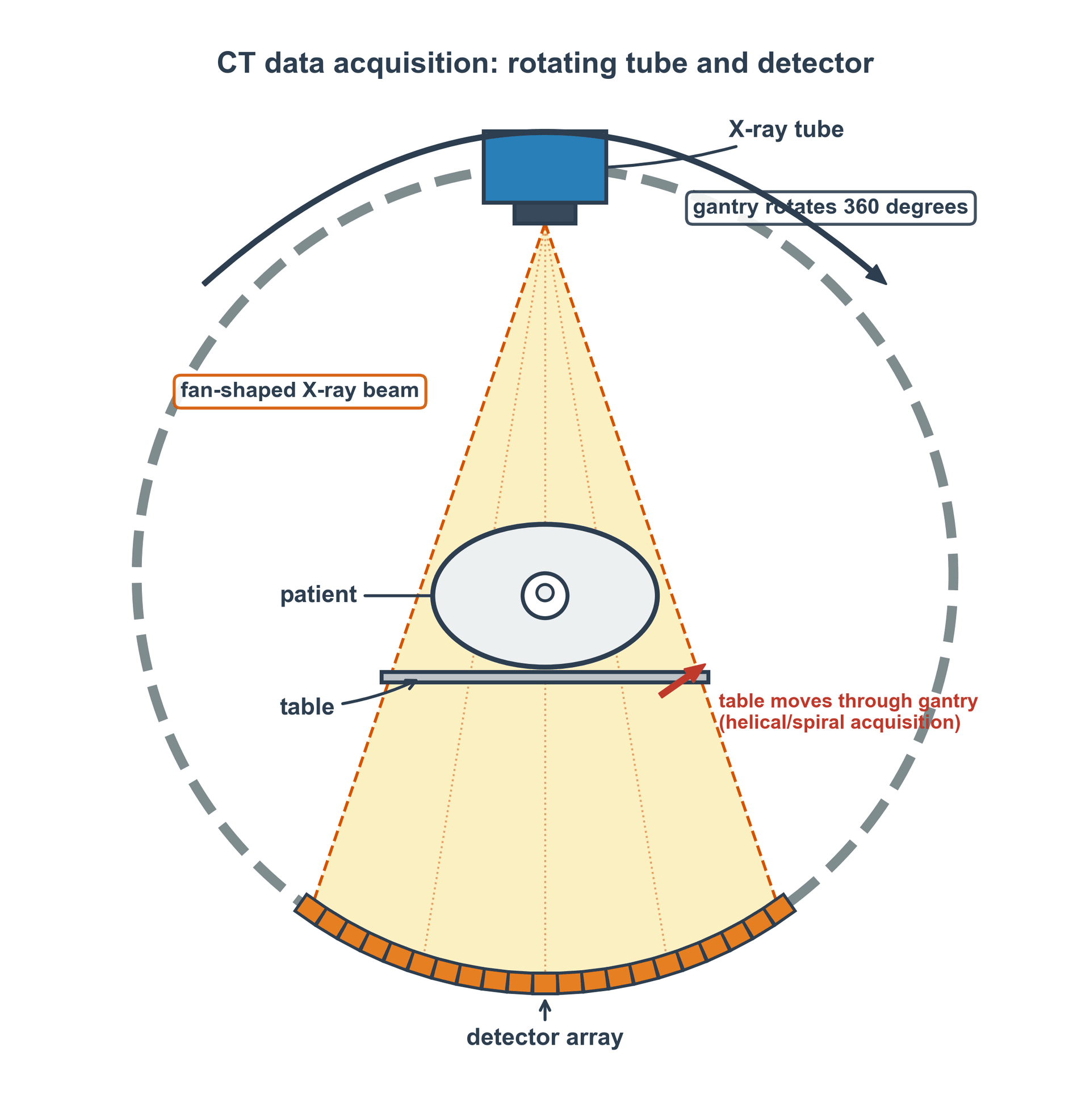
- CT uses a rotating X-ray tube and detector array to acquire cross-sectional images, eliminating superimposition.
- Hounsfield Units (HU) quantify tissue density: water = 0, air = -1000, dense bone = +1000, metal = +3000.
- CT delivers 100-300 times more radiation than a plain radiograph of the same region.
- Multiplanar reconstruction (MPR) and 3D volume rendering are generated from axial data without additional radiation.
- Window and level settings determine which HU range is displayed — bone window and soft tissue window show different pathology.
- “CT is the gold standard for complex fracture characterisation, especially acetabular fractures, tibial plateau, and calcaneus.
- “Dual-energy CT can differentiate urate crystals (gout) from calcium — increasingly used in crystal arthropathy diagnosis.
- “Metal artefact reduction sequences (MARS) improve imaging around orthopaedic implants but do not eliminate artefact completely.
- “CT angiography is essential in knee dislocation to exclude popliteal artery injury before reduction.
- “Always justify CT with clear clinical indication — the ALARA principle applies with even greater urgency given high doses.
CT principles are examined in both physics viva stations and clinical decision-making scenarios. You must understand: Hounsfield Units and their derivation, window/level settings, radiation dose compared to plain radiography, specific orthopaedic indications (acetabular fractures, tibial plateau fractures, spinal injuries), and the role of 3D reconstructions in preoperative planning. A common viva trap is failing to mention the significantly higher radiation dose compared to plain radiography when discussing CT indications.
FACTSCT Indications in Orthopaedics
Hook:FACTS: CT gives you the facts about fracture geometry that plain films cannot reveal.
AFOOTHounsfield Unit Reference Points
Hook:AFOOT through the Hounsfield scale: Air, Fat, 0-water, Organs, then hard Tissue.
Overview
Computed tomography (CT) revolutionised orthopaedic imaging by eliminating the superimposition problem inherent to plain radiography. By acquiring cross-sectional images, CT allows direct visualisation of fracture geometry, articular surface congruity, fragment displacement, and the relationship of bone to surrounding soft tissues in all three planes.
In orthopaedic practice, CT is primarily used for: complex fracture characterisation (especially intra-articular fractures), preoperative planning, postoperative assessment of reduction and implant position, assessment of union and nonunion, tumour staging, and evaluation of spinal pathology. Its superior spatial resolution for cortical bone (0.5-1mm) far exceeds MRI, making it the modality of choice when precise bony anatomy is needed.
The major disadvantage of CT is radiation dose — a single CT scan of the pelvis delivers 100-300 times more radiation than an AP pelvic radiograph. This makes clinical justification and dose optimisation essential for every CT requested.
Superior spatial resolution for cortical bone (0.5-1mm). Cross-sectional imaging eliminates superimposition. Multiplanar reconstruction (MPR) and 3D volume rendering from a single acquisition. Fast acquisition (seconds). Excellent for fracture characterisation, preoperative planning, and postoperative implant assessment. Can identify subtle non-displaced fractures missed by plain radiography. CT angiography for vascular assessment in dislocations.
High radiation dose (2-20 mSv depending on region). Significant metal artefact from orthopaedic implants (beam hardening and photon starvation). Limited soft tissue contrast compared to MRI — cannot reliably evaluate ligaments, cartilage, or bone marrow oedema. Cost significantly higher than plain radiography. Not portable — patient must travel to the CT scanner. Iodinated contrast carries risks of allergy and nephrotoxicity.
Systematic Approach
Systematic Approach to CT Interpretation in Orthopaedics
A structured approach to CT interpretation prevents missed findings and ensures comprehensive assessment. For every orthopaedic CT, apply the following systematic review:
- What to Assess
- Confirm correct region scanned, check for incidental findings at scan margins
- Key Questions
- Is the entire region of interest captured? Are there additional pathologies at the scan boundaries?
- What to Assess
- Scan systematically through cortical bone in all three planes (axial, coronal, sagittal)
- Key Questions
- Are all cortical surfaces intact? Any fracture lines, cortical breaks, or periosteal reaction?
- What to Assess
- Assess joint surface congruity in the plane perpendicular to the articular surface
- Key Questions
- Any step, gap, or depression? Quantify displacement in millimetres. Any intra-articular fragments?
- What to Assess
- Axes, rotation, angulation, subluxation
- Key Questions
- Is the joint congruent? Any rotational malalignment? Measure specific angles as needed.
- What to Assess
- Haematomas, effusions, soft tissue swelling, vascular injury, gas
- Key Questions
- Any expanding haematoma? Joint effusion? Soft tissue gas (open fracture)? Vascular contrast extravasation?
- What to Assess
- Global fracture pattern, fragment relationships, preoperative planning
- Key Questions
- What is the overall fracture geometry? Which surgical approach best addresses all major fragments?
Always review CT on BOTH bone and soft tissue windows. A common examination pitfall is identifying the fracture on bone windows but missing an expanding haematoma, vascular injury, or compartmental swelling visible only on soft tissue windows. In spinal trauma, always assess the spinal canal on soft tissue windows for retropulsed fragments and epidural haematoma.
CT Physics and Acquisition
Data Acquisition
A CT scanner consists of an X-ray tube mounted on a rotating gantry opposite a detector array. The tube rotates continuously around the patient (360 degrees per rotation in approximately 0.3-0.5 seconds on modern scanners), emitting a fan-shaped or cone-shaped X-ray beam. As the beam passes through the patient, different tissues attenuate (absorb and scatter) the beam to varying degrees. The detectors on the opposite side measure the intensity of the transmitted beam at thousands of angles around the patient.
Modern multi-detector CT (MDCT) scanners have 64 to 320 detector rows, allowing simultaneous acquisition of multiple slices per rotation. This dramatically reduces scan time and enables isotropic voxel resolution (equal resolution in all three planes), which is essential for high-quality multiplanar reconstructions.
Helical Acquisition and Pitch
Modern CT is acquired helically (spiral): the table moves continuously while the tube rotates, so the X-ray focus traces a helix relative to the patient and a whole volume is acquired in one breath-hold or pass. The single most examined acquisition parameter is pitch:
Pitch = table travel per gantry rotation / total nominal beam width (collimation)
- Pitch = 1: the table advances exactly one beam-width per rotation (contiguous acquisition).
- Pitch over 1: the table moves faster than the beam width — faster coverage and (all else equal) lower dose, but interpolation gaps can reduce z-axis resolution and increase helical (windmill) artefact.
- Pitch under 1: overlapping acquisition — higher z-axis resolution and better for fine detail, but at the cost of higher dose.
In practice, high pitch is chosen to freeze motion (polytrauma, paediatric or uncooperative patients) and low pitch for high-resolution work. The viva point is that pitch is the trade-off between speed/coverage, dose, and z-axis resolution; many scanners automatically adjust tube current with pitch to hold image quality constant, so always interpret pitch alongside the displayed CTDIvol rather than in isolation.
Hounsfield Units
The fundamental unit of CT imaging is the Hounsfield Unit (HU), named after Sir Godfrey Hounsfield who developed clinical CT. The HU is a linear transformation of the X-ray attenuation coefficient, normalised to water:
HU = 1000 × (μ tissue - μ water) / μ water
Where μ is the linear attenuation coefficient. This normalisation gives water a value of exactly 0 HU and air approximately -1000 HU, providing a standardised scale across all CT scanners.
- HU Range
- -1000
- Clinical Significance
- Reference lower bound; appears black on all windows
- HU Range
- -700 to -500
- Clinical Significance
- Low density due to air content; lung windows needed
- HU Range
- -50 to -100
- Clinical Significance
- Negative HU distinguishes fat from water — key for lipoma vs other tumours
- HU Range
- 0
- Clinical Significance
- Calibration reference point of the Hounsfield scale
- HU Range
- +40 to +80
- Clinical Significance
- Standard soft tissue density; visible on soft tissue windows
- HU Range
- +50 to +80
- Clinical Significance
- Fresh blood is slightly denser than muscle — useful for identifying acute haematoma
- HU Range
- +300 to +500
- Clinical Significance
- Trabecular bone; density reflects mineralisation status
- HU Range
- +800 to +1200
- Clinical Significance
- Dense cortical bone; visible on bone windows
- HU Range
- +3000 or more
- Clinical Significance
- Extremely dense; causes beam hardening and streak artefact
Window and Level Settings
A CT image dataset contains a far wider range of HU values than a monitor can display (typically 256 grey levels). Window width determines the range of HU values displayed, and window level (centre) determines the midpoint of this range.
- Width (HU)
- 2000-4000
- Level (HU)
- +300 to +500
- What It Shows
- Cortical detail, fracture lines, implant position, calcification
- Width (HU)
- 250-400
- Level (HU)
- +40 to +60
- What It Shows
- Muscle, haematoma, soft tissue masses, fluid collections
- Width (HU)
- 1500-2000
- Level (HU)
- -600
- What It Shows
- Air-containing structures, pneumothorax
- Width (HU)
- 80-100
- Level (HU)
- +35 to +40
- What It Shows
- Intracranial pathology (relevant for polytrauma assessment)
The critical concept for the examination is that changing window settings does NOT change the data — it simply changes which portion of the Hounsfield scale is displayed on screen. The same dataset can be viewed on bone windows (to assess fractures) and soft tissue windows (to assess haematomas) without rescanning the patient.
Image Reconstruction
Reconstruction Algorithms
Raw CT data (sinogram) must be mathematically reconstructed into cross-sectional images. Two main approaches exist:
Filtered Back Projection (FBP) is the traditional reconstruction algorithm that has been used since the development of clinical CT. It works by projecting the measured attenuation data back through the image matrix along the original ray paths, with mathematical filtering to remove blurring.
FBP is computationally fast and produces consistent, well-understood image characteristics. However, it is dose-inefficient — reducing the radiation dose increases image noise proportionally, and there is a minimum dose below which diagnostic quality is lost.
Convolution kernels (reconstruction filters) applied during FBP include:
- Soft tissue (smooth) kernel: Reduces noise but lowers spatial resolution — used for soft tissue assessment
- Bone (sharp) kernel: Maximises spatial resolution at the cost of increased noise — essential for fracture detection
- Lung kernel: Optimised for high-contrast air-tissue interfaces
FBP remains the standard of comparison for image quality assessment.
Multiplanar Reconstruction and 3D Rendering
One of the most powerful features of CT for orthopaedic surgery is the ability to generate multiplanar reconstructions (MPR) and 3D volume-rendered images from the original axial dataset without any additional radiation to the patient.
Coronal, sagittal, and oblique reformats generated from isotropic axial data. Essential for tibial plateau fracture assessment (coronal view for split/depression), acetabular fracture classification (coronal and sagittal), and spinal alignment assessment. Quality depends on slice thickness — thinner axial slices (0.5-1mm) produce better reformats than thick slices (3-5mm).
Three-dimensional surface reconstructions that provide an intuitive global view of complex fracture patterns. Invaluable for preoperative planning of acetabular fractures, complex periarticular fractures, and deformity correction surgery. Can digitally subtract overlying structures (e.g., show only the posterior column of the acetabulum). The surgeon can rotate the 3D model to understand fracture geometry from any angle. Increasingly used for 3D printing of patient-specific fracture models for preoperative planning.
CT Artefacts in Orthopaedic Imaging
CT artefacts are particularly relevant in orthopaedic practice because metallic implants are extremely common in the patient population.
- Cause
- Preferential absorption of low-energy photons by dense material (bone or metal)
- Appearance
- Dark bands between dense structures (Hounsfield bar between petrous bones); cupping artefact
- Reduction Strategies
- Beam hardening correction algorithms, increased kVp, hardware filtering
- Cause
- Photon starvation and beam hardening from orthopaedic implants
- Appearance
- Bright and dark streaks radiating from metallic hardware, obscuring adjacent anatomy
- Reduction Strategies
- Metal artefact reduction sequences (MARS/O-MAR/SEMAR), dual-energy CT, increased kVp, increased mAs
- Cause
- Voxel containing multiple tissue types is assigned their average HU value
- Appearance
- Blurring of interfaces; small fracture lines may be missed if slice is too thick
- Reduction Strategies
- Thinner slice thickness (0.5-1mm); volumetric acquisition
- Cause
- Patient movement during acquisition
- Appearance
- Blurring, double contours, streak patterns
- Reduction Strategies
- Faster scan time (wider detectors), immobilisation, breath-hold for torso scans
- Cause
- Miscalibrated detector element
- Appearance
- Concentric ring pattern centred on the rotation axis
- Reduction Strategies
- Detector calibration, quality assurance programme
Metal artefact reduction (MAR) is increasingly important as the orthopaedic population with existing implants grows. Vendor-specific algorithms (O-MAR by Philips, SEMAR by Canon, iMAR by Siemens) use iterative techniques to reduce streak artefact around metal hardware. Dual-energy CT approaches can also help by generating virtual monoenergetic images at higher keV, which are less affected by beam hardening. However, no current technique completely eliminates metal artefact — MRI with metal artefact reduction sequences (MAVRIC/SEMAC) may be preferable for soft tissue assessment around implants.
Orthopaedic Applications
Choosing CT vs Other Modalities
A frequent viva theme is justifying CT over an alternative. The clinical question — bone geometry, soft tissue, marrow, or vascular — should drive modality choice, not habit.
- First Choice
- CT
- Why / When CT Instead
- Best modality — quantifies step, gap, depression and fragment number for surgical planning
- First Choice
- MRI
- Why / When CT Instead
- CT has poor soft-tissue contrast; reserve CT arthrography for when MRI is contraindicated or unavailable
- First Choice
- MRI
- Why / When CT Instead
- CT can miss non-displaced fractures; dual-energy virtual non-calcium CT is a sensitive but less specific alternative when MRI is not available
- First Choice
- CT angiography
- Why / When CT Instead
- Fast, accurate exclusion of popliteal/limb arterial injury before or after reduction
- First Choice
- Joint aspiration; DECT adjunct
- Why / When CT Instead
- Dual-energy CT non-invasively maps urate when aspiration is negative or not feasible
- First Choice
- MRI (or US)
- Why / When CT Instead
- MRI superior for marrow and soft-tissue extent; CT used when MRI contraindicated or for gas/foreign body
- First Choice
- Plain radiography
- Why / When CT Instead
- Always first-line — CT only when films are insufficient for the decision at hand
CT in Fracture Assessment
CT is most valuable when plain radiographs suggest a complex fracture that requires detailed characterisation for surgical planning. The key orthopaedic trauma indications include:
Acetabular Fractures: CT is considered mandatory for all acetabular fractures. It changes the Letournel-Judet classification in up to 40% of cases compared to plain films alone. CT reveals: column involvement, wall fragments, marginal impaction (the 'gull sign'), intra-articular fragments, femoral head injury, and dome arc measurements.
Tibial Plateau Fractures: CT quantifies articular depression depth (greater than 2-3mm is a common surgical threshold), identifies split fragments, reveals posterior column involvement (often missed on plain films), and helps plan surgical approach.
Calcaneal Fractures: CT with coronal reformats demonstrates the posterior facet depression, calcaneocuboid joint involvement, sustentaculum tali fragment position, and allows measurement of the Bohler angle in the sagittal plane.
Pilon Fractures: CT defines the articular injury pattern, identifies the number and position of articular fragments, and guides the surgical approach.
Spinal Injuries: CT is the primary investigation for thoracolumbar burst fractures, assessing canal compromise, posterior element fractures, and vertebral body comminution.
CT is indispensable for preoperative planning of these injuries.
Radiation Dose and Safety
CT delivers substantially higher radiation doses than plain radiography and is the single largest contributor to medical radiation exposure in developed countries. Understanding CT dose metrics and optimisation strategies is essential for fellowship examinations.
CT Dose Metrics
- Effective Dose (mSv)
- 0.1-0.5
- Equivalent Plain Radiographs
- 10-50x limb X-ray
- Equivalent Background Radiation
- 1-8 weeks
- Effective Dose (mSv)
- 2-4
- Equivalent Plain Radiographs
- 100-200x C-spine X-ray
- Equivalent Background Radiation
- 8-16 months
- Effective Dose (mSv)
- 5-10
- Equivalent Plain Radiographs
- 3-7x lumbar X-ray series
- Equivalent Background Radiation
- 2-4 years
- Effective Dose (mSv)
- 6-10
- Equivalent Plain Radiographs
- 8-14x AP pelvis X-ray
- Equivalent Background Radiation
- 2-4 years
- Effective Dose (mSv)
- 10-20
- Equivalent Plain Radiographs
- 500-1000x chest X-ray
- Equivalent Background Radiation
- 4-7 years
- Effective Dose (mSv)
- 20-30
- Equivalent Plain Radiographs
- 1000-1500x chest X-ray
- Equivalent Background Radiation
- 7-12 years
A single polytrauma CT (head, cervical spine, chest, abdomen, pelvis) delivers approximately 20-30 mSv — equivalent to 7-12 years of natural background radiation. While this is justified in the acute trauma setting, the cumulative dose from serial CT imaging (follow-up, surveillance) must be considered, particularly in young patients. Always ask: 'Can this clinical question be answered by plain radiography, ultrasound, or MRI instead?'
CT Dose Metrics Defined
A frequent physics-viva trap is to quote effective dose (mSv) without knowing the quantities the scanner actually reports. Distinguish three things:
- Unit
- mGy
- What It Represents
- Average absorbed dose within the scanned volume for the chosen protocol; a measure of dose intensity displayed on the console, independent of scan length
- Unit
- mGy·cm
- What It Represents
- CTDIvol multiplied by scan length — reflects the total energy imparted, so it accounts for how much of the body was scanned
- Unit
- mSv
- What It Represents
- DLP multiplied by a region-specific conversion coefficient (the k-factor), weighting for the radiosensitivity of the organs in the scanned region; allows stochastic-risk comparison across examinations and body regions
The key concept: CTDIvol and DLP are physical dose quantities measured on a standard phantom, whereas effective dose is a calculated, risk-weighted estimate (not a measured patient dose). The k-factor is larger for the trunk (radiosensitive viscera) and small for the extremities — which is why a limb CT carries a far lower effective dose than its CTDIvol alone might suggest. Diagnostic reference levels (DRLs) are benchmarked in CTDIvol and DLP, not mSv.
Dose Optimisation
Automatic tube current modulation (adjusts mAs to patient size and body region). Iterative reconstruction (40-60% dose reduction). Low-kVp protocols for extremities. Scan length limitation (only scan the region of interest). Appropriate clinical indication and justification for every scan.
Use plain radiography as first-line investigation. Reserve CT for when plain films are insufficient for clinical decision-making. Avoid repeat CT when previous imaging can answer the question. Use MRI for soft tissue questions (ligaments, bone marrow oedema) rather than CT. Consider low-dose CT protocols for follow-up imaging.
SLIMCT Dose Reduction Strategies
Hook:SLIM the dose: CT is the biggest radiation contributor in medical imaging, so every reduction matters.
Dual-Energy CT
Dual-energy CT (DECT) acquires data at two different kVp settings simultaneously, allowing material decomposition based on the energy-dependent attenuation properties of different tissues. This has several orthopaedic applications:
- Mechanism
- Urate crystals have a unique dual-energy signature different from calcium
- Clinical Utility
- Non-invasive diagnosis of gout with reported sensitivity of 78-100% and specificity of 89-100%; can detect asymptomatic tophi
- Mechanism
- Subtraction of calcium signal reveals underlying bone marrow oedema
- Clinical Utility
- Detection of occult fractures (bone bruises) without MRI — useful in acute trauma when MRI is unavailable or contraindicated
- Mechanism
- Virtual monoenergetic images generated at higher keV reduce beam hardening
- Clinical Utility
- Improved visualisation around orthopaedic implants compared to conventional CT; 130-190 keV virtual monoenergetic images optimal
- Mechanism
- Collagen-rich structures have different dual-energy signatures
- Clinical Utility
- Emerging application for Achilles tendon assessment and ligament integrity, though MRI remains superior
Dual-energy CT can identify monosodium urate crystal deposits as small as 2mm, even in the absence of tophi visible on physical examination. The crystals are colour-coded green on commercial DECT software (calcium is coded purple/blue). False positives can occur with nail bed artefact, skin calluses, and motion artefact. This is increasingly asked about in fellowship examinations as it represents a genuine paradigm shift in gout diagnosis.
Guidelines, Registries & Global Practice
CT is the single largest contributor to medical radiation exposure worldwide. Across high-income health systems, CT accounts for only a minority of imaging studies (typically under 10% of examinations) yet contributes the majority (around 60-70%) of the collective dose from diagnostic radiology — the central justification for diagnostic reference levels (DRLs) and the ALARA principle. CT utilisation continues to rise globally, fastest in middle-income settings as scanner access expands, which makes appropriate-use criteria as relevant in resource-limited settings as in tertiary centres.
Global Epidemiology of CT Use
- CT volumes per capita are highest in the United States, Japan, and parts of Europe and lowest in low-resource settings where access — not over-use — is the dominant problem.
- Orthopaedic CT demand is driven by the ageing population, rising fragility-fracture burden, and the growing prevalence of in-situ metalwork (revision arthroplasty volumes are increasing across all major arthroplasty registries, including the NJR, AJRR, AOANJRR, and Scandinavian registries), which increases the need for metal-artefact-reduction CT.
Side-by-Side Society Guidance
- Core Position
- Evidence-based appropriateness ratings; plain radiography first-line, CT reserved for defined indications
- Practical Emphasis
- Structured 1-9 appropriateness scoring per clinical scenario; clinical decision support at order entry
- Core Position
- Referral guidelines (Making Best Use of Radiology) with justification for every exposure
- Practical Emphasis
- Explicit justification and optimisation duties under ionising-radiation regulation
- Core Position
- Pan-European DRLs and dose-audit culture
- Practical Emphasis
- National DRLs as benchmarks; routine dose audit and feedback
- Core Position
- CT mandatory for characterising complex intra-articular fractures (acetabulum, plateau, pilon, calcaneus)
- Practical Emphasis
- CT-based classification and 3D planning before periarticular fixation
- Core Position
- Justification, optimisation, dose-registry building in all settings
- Practical Emphasis
- Capacity-building and protocol standardisation in limited-resource systems
High- vs Limited-Resource Practice Variation
- Well-resourced settings: routine thin-slice MDCT with iterative (or deep-learning) reconstruction, automatic tube-current modulation, dual-energy capability, and vendor MAR; CT is standard for preoperative planning of complex fractures and for 3D-printed patient-specific models.
- Limited-resource settings: older single- or few-slice scanners, limited dual-energy and MAR availability, and constrained access mean plain radiography (and, where available, MRI) carries more of the diagnostic load. Justification matters even more where each scan competes for scarce capacity, and protocol optimisation and shared reference levels are the highest-yield safety interventions.
Diagnostic reference levels, not billing pathways, are the appropriate global benchmark for governing CT use — dose audit against DRLs is recommended by ICRP, the IAEA, and national regulators regardless of health-system funding model.
Clinical Decision Scenarios
Practise clinical reasoning and management decisions out loud
“A 45-year-old female has sustained an acetabular fracture in a road traffic collision. Plain radiographs show a both-column fracture pattern. You request a CT scan.”
“An examiner shows you a CT scan of a knee with significant metal streak artefact from a previous tibial plateau plate. They ask you to explain the artefact and describe strategies to improve image quality.”
“A concerned parent asks about the radiation risk of a CT scan ordered for their 12-year-old child who has a complex tibial plateau fracture.”
Hounsfield Units
- Water = 0 HU (reference), Air = -1000 HU, Fat = -50 to -100 HU
- Muscle = +40-80 HU, Cancellous bone = +300-500 HU, Cortical bone = +800-1200 HU
- HU = 1000 x (mu tissue - mu water) / mu water
- Changing window/level does NOT change data — only changes display
Key Orthopaedic Indications
- Acetabular fractures: MANDATORY — changes classification in up to 40%
- Tibial plateau: quantifies depression, reveals posterior column involvement
- Calcaneus: posterior facet assessment on coronal reformats
- Spinal trauma: canal compromise, posterior element fractures
- CT angiography in knee dislocation for popliteal artery assessment
Radiation Dose
- CT delivers 100-300x more radiation than plain radiography of same region
- CT accounts for 67% of medical radiation dose but only 5% of imaging volume
- Extremity CT: 0.1-0.5 mSv; Pelvis CT: 6-10 mSv; Polytrauma CT: 20-30 mSv
- Iterative reconstruction reduces dose by 40-60% vs filtered back projection
Metal Artefact
- Beam hardening: preferential low-energy photon absorption by metal
- Photon starvation: complete absorption at some projection angles
- Reduction: higher kVp, MAR software (O-MAR/iMAR/SEMAR), dual-energy CT at 130-190 keV
- MRI with MAVRIC/SEMAC may be superior for soft tissue around implants
Dual-Energy CT
- Gout: urate crystal detection (87% sensitivity, 84% specificity)
- Virtual non-calcium: detects bone marrow oedema without MRI
- Virtual monoenergetic images: reduce metal artefact
- False positives: nail bed, skin calluses, motion artefact
Evidence Base
CT vs Plain Radiographs for Acetabular Fracture Displacement
- Compared to CT, plain radiographs had poor sensitivity for detecting articular step deformity (25%) in displaced acetabular fractures.
- For fractures involving a single column of the acetabulum, plain radiographs detected step deformity with 0% sensitivity.
- In osteotomised canine specimens, CT measured step and gap displacement far more accurately than plain radiographs relative to true displacement.
Spiral CT with 3D Reconstruction in Tibial Plateau Fractures
- Tibial plateau fractures were underestimated on plain films in 18 of 42 cases (43%) compared with spiral CT and 3D reconstruction.
- In the 22 cases planned with both modalities, the surgical plan based on plain films was modified after CT in 13 cases (59%).
- Spiral CT 3D reconstructions gave a more accurate demonstration of fracture geometry and a more precise preoperative plan.
CT evidence consistently supports its use for complex periarticular fracture characterisation.