Fundamental principles of moment arms, lever systems, and mechanical advantage in the musculoskeletal system. Essential biomechanics for understanding force transmission, joint mechanics, and clinical applications in orthopaedic surgery.
- Moment = Force × perpendicular distance to axis of rotation
- Third-class levers most common (MA <1, speed/ROM prioritized)
- Patella increases quadriceps moment arm 20-30% at cost of high PFJRF
- Moment arms vary with joint angle - peak torque mid-range (e.g. biceps at 90°)
- Muscles generate forces several times external loads due to MA <1
- “Biceps generates max torque at ~90° flexion where moment arm peaks
- “Forward head posture increases load moment arm, overloading extensors (text neck)
- “Patellectomy reduces knee extension strength 20-30% requiring greater muscle force
- “Joint reaction forces reach 2-5× body weight during walking/running
Core basic science topic frequently examined in vivas and MCQs. Examiners expect clear definitions of moment, moment arm, and mechanical advantage, plus ability to classify lever systems with clinical examples. Know how moment arms change with joint position and implications for muscle function.
Fundamental Concepts
Moments and Torque
Definition of Moment
A moment, also called torque, is the rotational equivalent of linear force. When a force acts on a rigid body at some distance from an axis of rotation, it creates a tendency for the body to rotate around that axis. The magnitude of this rotational effect depends on both the magnitude of the force and the perpendicular distance from the force vector to the axis.
Mathematically, the moment is expressed as:
Moment (M) = Force (F) × Perpendicular distance (d)
The units are Newton-meters (N·m) in SI units or foot-pounds (ft-lb) in imperial units. In the musculoskeletal system, moments are commonly expressed in N·m or N·cm.
Moment Arm
The moment arm (also called lever arm or force arm) is the perpendicular distance from the line of action of the force to the axis of rotation (fulcrum). This is a critical distinction: it is not simply the distance from the point of force application to the fulcrum, but specifically the perpendicular distance.
If a force acts directly through the axis of rotation (moment arm = 0), no moment is produced regardless of force magnitude. This explains why muscle forces produce no joint torque when the muscle line of action passes through the joint center, which occurs at specific joint angles for some muscles.
The perpendicular nature of the moment arm means that as the angle between the force vector and the lever changes, the effective moment arm changes, even if the anatomical positions remain constant. This geometric relationship is fundamental to understanding how muscle torque varies throughout the range of motion.
Direction of Rotation
Moments are vector quantities with both magnitude and direction. The direction follows the right-hand rule: if the fingers of the right hand curl in the direction of rotation, the thumb points in the direction of the moment vector. Conventionally, counterclockwise moments are positive and clockwise moments are negative, though this convention can be reversed depending on the coordinate system chosen.
In equilibrium analysis, the sum of all moments about any point must equal zero. This principle is essential for calculating unknown forces in biomechanical systems.
Overview
Fundamental Biomechanical Concepts
- Definition: Rotational effect of a force about an axis
- Formula: M = F × d (force × perpendicular distance)
- Units: Newton-meters (Nm)
- Direction: Clockwise or counterclockwise
- Equilibrium: Sum of moments = 0 for balance
- Definition: Perpendicular distance from force line of action to axis of rotation
- Determines: Mechanical advantage of muscle/force
- Variable: Changes with joint angle
- Clinical relevance: Affects force required for movement
- Optimization: Surgical positioning of muscles/implants
Mechanical Advantage
- Definition
- Ratio of output to input force
- Formula
- MA = Resistance arm / Effort arm
- Clinical Example
- Biceps has MA less than 1 (speed over force)
- Definition
- MA greater than 1
- Formula
- Load arm shorter than effort arm
- Clinical Example
- Rare in body; nutcracker jaw action
- Definition
- MA less than 1
- Formula
- Load arm longer than effort arm
- Clinical Example
- Most limb movements; biceps, quadriceps
- Definition
- Inverse of MA
- Formula
- VR = Effort arm / Resistance arm
- Clinical Example
- Speed gained = force sacrificed
The human body is designed primarily for speed and range of motion rather than force amplification. Most muscle lever systems have mechanical advantage less than 1, meaning muscles must generate forces many times greater than the external load.
Principles of Lever Mechanics
Musculoskeletal motion is governed by rotational mechanics: muscles generate force, but it is the moment (force multiplied by its perpendicular distance from the joint axis) that turns a joint. Three ideas underpin the whole topic:
- Moment (torque) quantifies the turning effect of a force about an axis; it is zero when the force passes through the axis.
- Moment arm is the perpendicular distance from the line of action of a force to the axis of rotation, and it changes continuously as a joint moves through its range.
- Mechanical advantage is the ratio of load to effort (equivalently effort arm to load arm); almost every limb muscle operates at mechanical advantage less than 1, trading force for speed and range of motion.
Because most levers are third-class with mechanical advantage less than 1, muscle and joint reaction forces are several times the external load - the unifying explanation for high in-vivo joint forces, implant loading, and the surgical importance of restoring moment arms.
Anatomy
Anatomical Lever Systems
- Arrangement
- Fulcrum between effort and load
- Characteristics
- Can amplify force OR speed
- Body Examples
- Atlanto-occipital joint (head nodding), triceps at elbow
- Arrangement
- Load between fulcrum and effort
- Characteristics
- Always force amplification (MA greater than 1)
- Body Examples
- Ankle plantarflexion (heel raise); rare in body
- Arrangement
- Effort between fulcrum and load
- Characteristics
- Always speed amplification (MA less than 1)
- Body Examples
- Most limb movements: biceps, hip flexors, quadriceps
Key Muscle Moment Arms
- Deltoid (abduction): 2-3 cm at 90° abduction
- Biceps (flexion): 4-5 cm at 90° flexion
- Triceps (extension): 2-3 cm at 90° flexion
- Rotator cuff: 1-2 cm (short moment arm)
- Wrist flexors/extensors: 1-2 cm
- Gluteus medius: 5-7 cm (abductor moment arm)
- Quadriceps (via patella): 4-5 cm at 60° flexion
- Hamstrings: 3-4 cm at 45° flexion
- Gastrocnemius/Soleus: 5-6 cm (long Achilles moment arm)
- Hip abductors: Critical for single-leg stance
Anatomical Pulleys
- Structure
- Sesamoid in quadriceps tendon
- Function
- Increases quad moment arm by 30%
- Clinical Relevance
- Patellectomy weakens extension significantly
- Structure
- Peroneal tendon pulley
- Function
- Redirects peroneal tendons posteriorly
- Clinical Relevance
- Subluxation causes lateral ankle instability
- Structure
- A1-A5 annular pulleys
- Function
- Prevent bowstringing of flexor tendons
- Clinical Relevance
- A2, A4 critical for function; trigger finger at A1
- Structure
- Intertubercular sulcus
- Function
- Redirects long head of biceps
- Clinical Relevance
- Pulley lesions cause subluxation/rupture
Lever Classifications
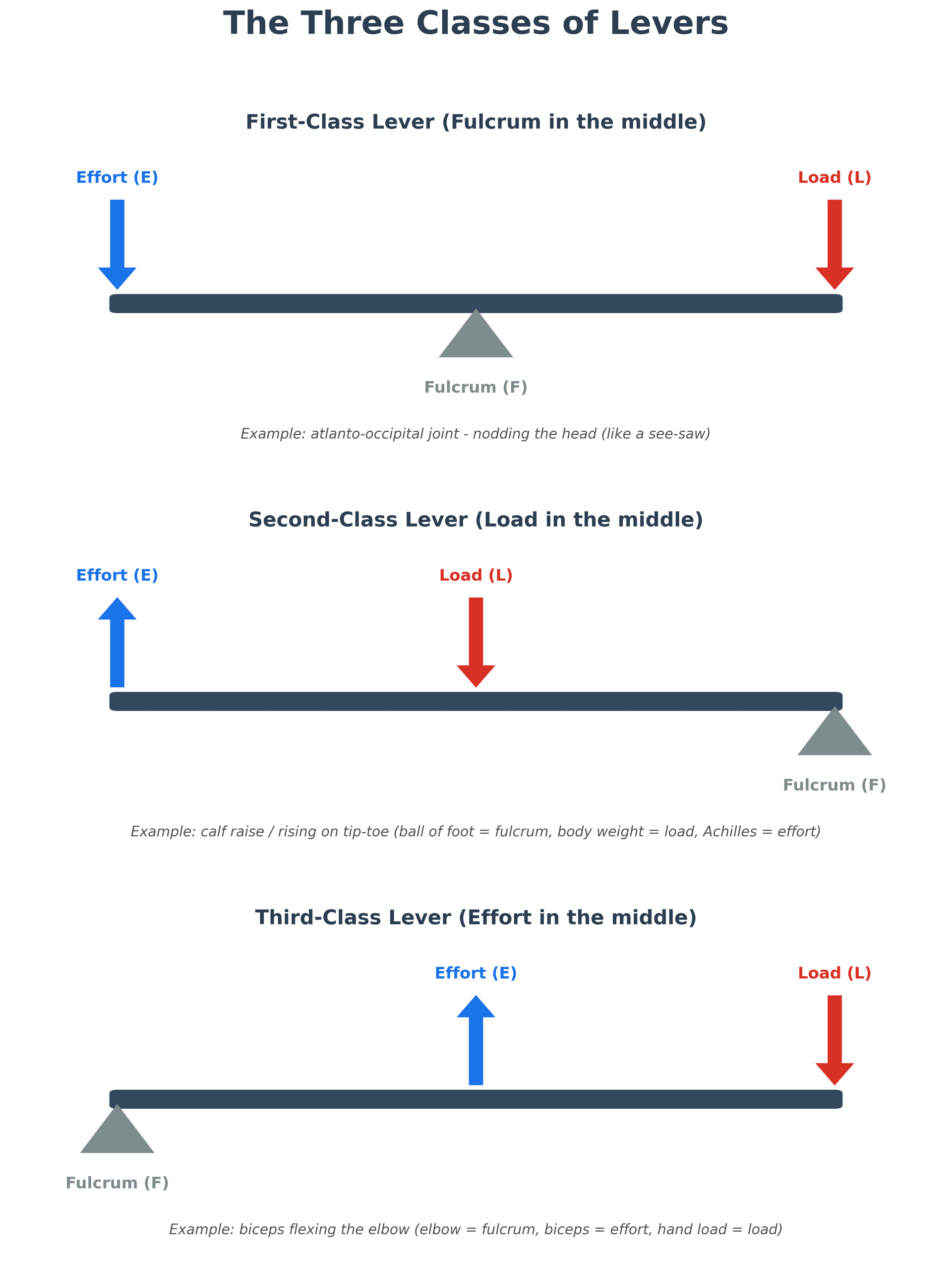
First-Class Levers
Definition and Characteristics
In first-class levers, the fulcrum is positioned between the effort and the load. This arrangement is analogous to a seesaw or balance scale. The mechanical advantage can be greater than, equal to, or less than 1 depending on the relative positions of the effort and load.
First-class levers are relatively uncommon in the musculoskeletal system but do occur in specific anatomical locations.
Clinical Examples
Atlantooccipital Joint (Head on Spine):
The classic example is nodding the head. The fulcrum is the atlantooccipital joint. The load is the weight of the head anterior to the joint (the face and frontal skull). The effort is provided by the posterior cervical extensor muscles pulling posteriorly on the occiput and upper cervical spine.
When the head is balanced directly over the spine, minimal muscle force is required. As the head tilts forward (such as when looking down at a smartphone), the moment arm of the head weight increases dramatically, requiring substantial extensor muscle force to maintain position. This explains "text neck" syndrome where chronic forward head posture overloads the cervical extensors.
Triceps and Olecranon:
Some biomechanists classify elbow extension as a first-class lever with the fulcrum at the elbow joint, the effort provided by triceps insertion on the olecranon posterior to the joint, and the load (resistance to extension) anterior to the joint. However, this classification is debatable and depends on how the load is defined.
Temporomandibular Joint:
Opening the jaw against resistance involves the TMJ as a fulcrum, with digastric muscles providing downward effort on the mandible and the resistance (food, bite block) located anteriorly between the teeth.
Functional Significance
First-class levers provide balance and can amplify either force or speed depending on relative arm lengths. In the musculoskeletal system, they typically function to balance opposing forces or to allow small muscle displacements to produce controlled movements over a balanced range.
Second-Class Levers
Definition and Characteristics
In second-class levers, the load is positioned between the fulcrum and the effort. This arrangement always provides mechanical advantage greater than 1, amplifying force at the expense of speed and displacement. A wheelbarrow is the classic mechanical example.
Second-class levers are uncommon in the musculoskeletal system, primarily because force amplification is less important than speed for most human movements.
Clinical Examples
Calf Raise (Plantarflexion):
The most commonly cited example is rising onto the toes. The fulcrum is the metatarsophalangeal joints (ball of the foot). The load is body weight acting through the ankle joint (approximately midfoot). The effort is the Achilles tendon pulling upward on the calcaneus (heel).
The effort arm extends from the MTP joints to the posterior calcaneus (approximately 12-15 cm), while the load arm extends from the MTP joints to the ankle joint (approximately 8-10 cm). This gives mechanical advantage of approximately 1.2 to 1.5, one of the few musculoskeletal examples where MA exceeds 1.
This force amplification allows the calf muscles to lift the entire body weight (plus any additional load carried) repeatedly during walking, running, and jumping. The calf muscles are among the strongest in the body relative to size, further enhancing plantarflexion force production.
Intertarsal Joints During Gait:
Some complex foot movements during the stance phase of gait can be analyzed as second-class levers, though the biomechanics are complicated by the multi-segmental nature of the foot and ground reaction force vector changes throughout stance.
Functional Significance
Second-class levers in the musculoskeletal system are specialized for force production rather than speed or range of motion. The plantarflexors exemplify this, generating large forces for propulsion during gait, jumping, and climbing stairs, though the range of ankle plantarflexion is more limited than dorsiflexion.
Third-Class Levers
Definition and Characteristics
In third-class levers, the effort is positioned between the fulcrum and the load. This arrangement always provides mechanical advantage less than 1, meaning the effort must exceed the load. However, this configuration amplifies speed and displacement, allowing small muscle contractions to produce large end-point movements.
Third-class levers are by far the most common type in the musculoskeletal system, present at nearly all major limb joints.
Clinical Examples
Elbow Flexion (Biceps Brachii):
The archetypal example is the biceps lifting a weight in the hand. The fulcrum is the elbow joint. The effort is the biceps inserting on the radial tuberosity approximately 4 to 5 centimeters distal to the elbow. The load is resistance in the hand, approximately 30 to 35 centimeters from the elbow.
Mechanical advantage is approximately 4:30 = 0.13, meaning the biceps must generate forces 7 to 8 times larger than the hand load. To lift a 5 kg weight, the biceps generates approximately 35 to 40 kg of force. However, when the biceps shortens just 2 centimeters, the hand moves through an arc of approximately 15 centimeters, a 7.5-fold displacement amplification.
Knee Extension (Quadriceps):
The quadriceps inserts on the tibial tuberosity via the patellar tendon, approximately 4 to 5 centimeters distal to the knee joint center. External loads (body weight during stance, resistance during leg extension exercise) act much farther from the knee. The mechanical advantage is typically 0.15 to 0.20, similar to the biceps.
The patella is a sesamoid bone that increases the moment arm of the quadriceps by elevating the patellar tendon anterior to the knee joint center. Patellectomy reduces the quadriceps moment arm by approximately 20 to 30 percent, requiring greater muscle force to produce the same knee extension torque.
Hip Abduction (Gluteus Medius):
The gluteus medius and minimus abduct the hip, with insertions on the greater trochanter approximately 5 to 6 centimeters from the hip joint center. The load arm for single-leg stance is the distance from the hip center to the center of mass of the body (approximately 10-12 cm), giving MA approximately 0.5.
During single-leg stance, the hip abductors must generate forces approximately 2 to 2.5 times body weight to stabilize the pelvis. Combined with the body weight acting on the femoral head, total hip joint reaction force reaches 2.5 to 3 times body weight during normal walking, increasing to 4 to 5 times body weight during running.
Shoulder Abduction (Deltoid):
The deltoid inserts on the lateral humerus approximately 10 to 12 centimeters from the glenohumeral joint center, while the center of mass of the arm is approximately 15 to 18 centimeters from the joint. During abduction, especially with external weights, the deltoid must generate very high forces.
This explains why rotator cuff tears (particularly supraspinatus) cause such functional impairment. The supraspinatus initiates abduction and depresses the humeral head, optimizing deltoid function. With supraspinatus loss, the deltoid pulls the humeral head superiorly instead of efficiently rotating it, compromising abduction strength and producing characteristic shoulder shrugging.
Functional Significance
Third-class levers dominate the musculoskeletal system because speed, range of motion, and fine motor control are more critical to human function than raw force amplification. Evolution has favored rapid, coordinated movements over the ability to lift extremely heavy loads with minimal muscle force.
The disadvantage is high muscle forces and joint reaction forces during routine activities, contributing to joint degeneration and overuse injuries. Understanding these mechanics guides surgical decision-making (preserving or reconstructing moment arms), rehabilitation (optimizing muscle strength to compensate for mechanical disadvantage), and joint replacement design (attempting to restore normal moment arms).
- fulcrumPosition
- Between effort and load
- mechanicalAdvantage
- Variable (can be greater or less than 1)
- musculoskeletalExamples
- Atlantooccipital joint (head nodding), TMJ
- advantageType
- Balance and control
- clinicalExample
- Text neck: forward head increases load moment arm, overloading posterior cervical muscles
- functionalRole
- Balancing opposing forces, controlled movements
- fulcrumPosition
- Load between fulcrum and effort
- mechanicalAdvantage
- Always greater than 1 (force amplification)
- musculoskeletalExamples
- Calf raise (MTP = fulcrum, ankle = load, Achilles = effort)
- advantageType
- Force amplification
- clinicalExample
- Plantarflexion: MA ~1.2-1.5 allows calf muscles to lift entire body weight repeatedly
- functionalRole
- Specialized for high force production (propulsion, jumping)
- fulcrumPosition
- Effort between fulcrum and load
- mechanicalAdvantage
- Always less than 1 (speed amplification)
- musculoskeletalExamples
- Biceps (elbow), quadriceps (knee), deltoid (shoulder), most limb muscles
- advantageType
- Speed and range of motion amplification
- clinicalExample
- Biceps: MA ~0.13, must generate 7-8× hand load, but small muscle shortening produces large hand displacement
- functionalRole
- Dominant system enabling rapid movements, large range of motion, fine motor control
Mnemonic
Hook:For Love, Load Position - 1-2-3
Force Couples
Levers explain how a single muscle force turns a joint, but many joints are controlled by a force couple - the other fundamental moment-producing arrangement, repeatedly relied on above (the deltoid and rotator cuff acting together at the shoulder), so it deserves naming.
a force couple is two equal, parallel, oppositely-directed forces acting along separate lines of action. Their linear (translational) effects cancel, so the net force is zero, but together they produce a pure moment equal to one force multiplied by the perpendicular distance between the two lines of action. A couple therefore generates rotation without translating the fulcrum - precisely what a joint needs to turn about a stable centre of rotation.
in a simple lever the fulcrum (joint) must resist a large reaction force; in a balanced force couple the opposing forces hold the centre of rotation stationary while still generating torque. If one limb of the couple is lost, the couple is unbalanced and the fulcrum migrates.
- Shoulder, coronal plane: the deltoid pulls the humeral head superiorly while the inferior rotator cuff (subscapularis, infraspinatus, teres minor) pulls it inferiorly; balanced, they create a stable fulcrum about which the deltoid abducts the arm. A massive cuff tear unbalances this couple - the deltoid's unopposed superior pull lets the head ride up and abduction fails (pseudoparalysis) despite an intact deltoid.
- Shoulder, transverse plane: subscapularis anteriorly balanced against infraspinatus and teres minor posteriorly centres the head in the glenoid. (Shoulder-specific cuff mechanics are developed in the dedicated shoulder and rotator-cuff topics.)
- Trunk and pelvis: the abdominal and erector spinae muscles, and the paired hip abductors, act as couples to control pelvic tilt and spinal rotation.
A lever turns a joint with a single force about a fulcrum that must resist a large reaction; a force couple turns it with two equal, opposite, parallel forces whose translations cancel (net force zero, pure moment = force × the distance between the two lines of action), keeping the fulcrum centred. The classic example is the deltoid-rotator-cuff coronal force couple: lose the cuff's inferior pull and the deltoid's unopposed superior pull lets the humeral head ride up, abolishing abduction (pseudoparalysis) even with an intact deltoid.
Moment Arms in Clinical Context
Variable Moment Arms
Changes Through Range of Motion
A critical concept often overlooked is that muscle moment arms are not constant; they vary as joints move through their range of motion. This variation profoundly affects muscle function and torque production capacity.
Biceps Brachii Moment Arm:
At full elbow extension (0 degrees), the biceps moment arm is approximately 2 to 3 centimeters because the muscle line of action passes relatively close to the joint center. As the elbow flexes to 90 degrees, the biceps moment arm increases to approximately 4 to 5 centimeters as the muscle courses farther anterior to the joint center. With further flexion beyond 90 degrees, the moment arm gradually decreases again.
This explains why the biceps generates maximum elbow flexion torque at mid-range (approximately 90 degrees of flexion), not at the extremes of motion. Combined with length-tension relationships (muscle generates maximum force at optimal length), the biceps is strongest in mid-range flexion.
Quadriceps Moment Arm:
The quadriceps moment arm also varies with knee position. At full extension, the patellar tendon line of action is nearly parallel to the tibia, creating a small moment arm. As the knee flexes, the patellar tendon angle relative to the tibia becomes more perpendicular, increasing the moment arm to a maximum at approximately 60 to 70 degrees of flexion. Beyond this, the moment arm gradually decreases.
The patella plays a crucial role as a spacer, maintaining the patellar tendon anterior to the knee joint center and optimizing the quadriceps moment arm. Patellectomy or patella baja (low-lying patella) reduces the quadriceps moment arm, requiring greater muscle force for knee extension and potentially contributing to early quadriceps fatigue and extensor mechanism dysfunction.
Deltoid Moment Arm:
During shoulder abduction, the deltoid moment arm is smallest at the starting position (arm at side) and increases as abduction proceeds to approximately 60 to 90 degrees, then decreases again at higher angles of abduction. This combines with the supraspinatus moment arm, which is greatest in the initial 30 degrees of abduction, creating complementary torque production throughout the abduction arc.
Clinical Implications
Surgical Decision-Making:
Procedures that alter muscle insertions or joint geometry must consider effects on moment arms. For example:
- Patellar tendon advancement (Maquet procedure) increases the quadriceps moment arm by anteriorizing the tibial tuberosity, reducing patellofemoral joint reaction force.
- Derotational osteotomies change muscle moment arms relative to rotational deformities.
- Joint replacement component positioning affects muscle moment arms; excessive posterior slope of the tibial component in TKA can reduce the quadriceps moment arm.
Rehabilitation:
Understanding moment arm variation guides exercise prescription. Strengthening should occur throughout the full range of motion because torque capacity and muscle activation patterns vary by joint angle. Weakness at specific angles may indicate either muscle strength deficits or biomechanical disadvantage at that position.
Injury Mechanisms:
Injuries often occur when external moments exceed muscle capacity to generate counteracting moments. This is most likely at positions where muscle moment arms are smallest (mechanical disadvantage) or at extreme ranges where length-tension relationships are suboptimal.
Joint Reaction Forces
Calculation Principles
Joint reaction forces result from the combined effects of muscle forces, external loads, and limb segment weights. Because most musculoskeletal levers operate with MA less than 1, muscle forces substantially exceed external loads, and joint reaction forces are often 2 to 6 times larger than external loads.
Consider elbow flexion holding a 10 kg weight:
- External load moment = 10 kg × 35 cm = 350 kg·cm
- Biceps moment arm = 4 cm
- Required biceps force = 350 / 4 = 87.5 kg
- Elbow joint reaction force = Biceps force + External load = 87.5 + 10 = 97.5 kg (approximately 10× the external load)
This simplified calculation ignores forearm weight and assumes the biceps acts alone, but illustrates the principle that joint forces far exceed external loads.
Hip Joint During Single-Leg Stance:
During single-leg stance, the hip abductors (primarily gluteus medius and minimus) must prevent pelvic drop on the contralateral side. The abductor moment arm is approximately 5 to 6 centimeters, while the body weight (minus stance leg) acts approximately 10 to 12 centimeters from the hip joint center.
For a 70 kg person:
- Body weight excluding stance leg = approximately 55 kg
- Load moment = 55 kg × 10 cm = 550 kg·cm
- Abductor moment arm = 5 cm
- Abductor force = 550 / 5 = 110 kg (approximately 2× body weight)
The hip joint reaction force is the vector sum of body weight and abductor force, typically 2.5 to 3 times body weight during normal walking. With faster walking or running, accelerations increase ground reaction forces and joint loads proportionally.
Knee Joint During Squatting:
During deep squatting, the external moment (body weight and any additional load acting through the knee joint center to the ground contact point) increases progressively with knee flexion as the moment arm lengthens. Simultaneously, the quadriceps moment arm changes, and the patellofemoral contact area shifts proximally on the patella.
At 90 degrees of knee flexion, patellofemoral joint reaction force can reach 3 to 5 times body weight, increasing to 7 to 8 times body weight at 120 degrees of flexion. This explains why deep squatting is discouraged in patients with patellofemoral arthritis or chondromalacia.
Clinical Relevance
Understanding joint reaction forces guides:
Patients with joint arthritis benefit from reducing activities that generate high joint forces. Using assistive devices (cane, crutches) reduces hip and knee forces by decreasing the external moment arm (bringing center of mass closer to joint).
Implants must withstand joint reaction forces often exceeding 3 to 5 times body weight during routine activities and up to 10 times body weight during high-demand activities. This drives materials selection and fixation methods.
Internal fixation devices experience forces related to joint reaction forces. Plates and screws must resist bending moments and shear forces that reflect the mechanical environment of the bone-implant construct.
Ground Reaction Force and External Joint Moments
The worked examples above use body weight as a static load, while the gait-laboratory section measures the ground reaction force (GRF) - the concept that links them is the external joint moment, the basis of all gait analysis.
- Ground reaction force: by Newton's third law, when the foot pushes on the ground the ground pushes back with an equal and opposite GRF. In quiet standing the vertical GRF equals body weight, but during gait acceleration adds inertial loading, so the vertical GRF rises above body weight (roughly 1.1 to 1.3 times body weight in walking and 2 to 3 times in running) and also has fore-aft and medio-lateral components.
- External moment: at each joint the external moment = GRF magnitude × the perpendicular distance from the GRF vector to that joint axis. Whichever side of the joint the GRF passes, it tends to rotate the joint that way, and the muscles must generate an equal and opposite internal moment to control it. This is why moving the GRF (or the centre of mass) relative to the joint - leaning the trunk, using a contralateral cane, a lateral-wedge insole, or a realignment osteotomy - changes joint load without changing body weight.
- Inverse dynamics: a gait laboratory combines the measured GRF (force plate) with limb kinematics (motion capture) and segment masses to calculate the net internal moment, power and estimated force at each joint throughout the gait cycle - turning the static free-body analysis above into a dynamic, instant-by-instant one.
- Worked clinical example - the knee adduction moment (KAM): during stance the GRF passes medial to the knee, creating an adduction (varus) external moment that loads the medial compartment. The KAM is the best surrogate for medial-compartment load and predicts medial-osteoarthritis progression; interventions that shorten the GRF-to-knee moment arm - lateral-wedge insoles, gait retraining (toe-out, trunk lean), a contralateral cane, or a valgus high tibial osteotomy - reduce the KAM and offload the medial compartment.
The ground reaction force (near body weight when standing, but 2 to 3 times body weight in running) acts at a perpendicular distance from each joint, creating the external joint moment that muscles must balance with an equal internal moment. Gait labs derive internal joint moments from GRF plus kinematics by inverse dynamics. Clinically, the knee adduction moment (GRF passing medial to the knee) is the key surrogate for medial-compartment load - reduced by lateral wedges, a contralateral cane, gait retraining, or a valgus HTO that shortens the GRF-to-knee lever arm.
Classification
Lever Classification Systems
- Arrangement
- Fulcrum between effort and load (E-F-L)
- Mechanical Advantage
- Can be greater than 1, equal to 1, or less than 1
- Example
- Atlantooccipital joint (head nodding)
- Arrangement
- Load between fulcrum and effort (F-L-E)
- Mechanical Advantage
- Always greater than 1 (force amplification)
- Example
- Calf raise: MTP fulcrum, ankle load, Achilles effort
- Arrangement
- Effort between fulcrum and load (F-E-L)
- Mechanical Advantage
- Always less than 1 (speed amplification)
- Example
- Biceps, quadriceps, deltoid - over 95% of body levers
MA greater than 1:
- Force amplification
- Sacrifice speed for power
- Rare in musculoskeletal system
MA less than 1:
- Speed and ROM amplification
- High muscle forces required
- Dominant in human body
External moment arm:
- Distance from external force to joint axis
- Increases with limb length
Internal moment arm:
- Distance from muscle force to joint axis
- Determined by anatomy
To identify lever class quickly:
- Find the fulcrum (joint)
- Locate the effort (muscle insertion)
- Identify the load (weight/resistance)
Memory trick: "FEL-3" → F(ulcrum)-E(ffort)-L(oad) = Third-class, and third-class levers comprise 95% of musculoskeletal system.
Clinical Assessment
Biomechanical Clinical Assessment
Trendelenburg gait:
- Indicates abductor weakness or reduced moment arm
- Pelvis drops on swing side
- Compensatory trunk lean toward stance leg
Assessment: Single-leg stance for 30 seconds; positive if pelvis drops or trunk compensates.
Manual muscle testing considerations:
- Position affects moment arm and force requirement
- Test at position of maximum mechanical advantage
- Compare to contralateral side
Dynamometry: Quantitative force measurement at standardized positions.
- Clinical Finding
- Trendelenburg gait
- Biomechanical Explanation
- Reduced abductor moment arm
- Clinical Finding
- Extensor lag, weak terminal extension
- Biomechanical Explanation
- Reduced quadriceps moment arm
- Clinical Finding
- Weakness despite intact muscle
- Biomechanical Explanation
- Altered lever arm geometry
- Clinical Finding
- Complete loss of function
- Biomechanical Explanation
- Zero moment arm (no force transmission)
Key clinical tests:
- Active extension: Assess for extensor lag (inability to fully extend against gravity)
- Passive patellar position: Alta/baja assessment
- Q-angle measurement: Affects resultant force vector
- Single-leg squat: Functional assessment of moment generation
Interpretation: Weakness despite intact muscle suggests mechanical (moment arm) problem.
Investigations
Radiographic Biomechanical Assessment
- Normal Value
- 40-50 mm
- Clinical Significance
- Abductor moment arm
- How to Measure
- Horizontal distance from head center to shaft axis
- Normal Value
- 125-135°
- Clinical Significance
- Affects offset and leg length
- How to Measure
- Angle between neck and shaft axes
- Normal Value
- 0.8-1.2
- Clinical Significance
- Patellar height, quadriceps MA
- How to Measure
- Patellar tendon length / patella length
- Normal Value
- Males 10-15°, Females 15-20°
- Clinical Significance
- Lateral patella force vector
- How to Measure
- ASIS to patella center to tibial tubercle
Standard AP pelvis:
- Femoral offset measurement
- Center-edge angle (acetabular coverage)
- Neck-shaft angle
Planning requirements:
- Magnification marker for accurate templating
- Comparison to contralateral side
Lateral knee radiograph:
- Insall-Salvati ratio (patellar height)
- Posterior tibial slope (affects moment)
Merchant/skyline view:
- Patellar tilt and subluxation
- Trochlear dysplasia assessment
How to measure femoral offset on AP pelvis:
- Draw line along femoral shaft axis
- Identify center of femoral head
- Measure perpendicular distance from head center to shaft axis
- Normal: 40-50 mm; compare to contralateral
Clinical relevance: Every mm of offset change alters abductor force requirement.
Management

Biomechanical Optimization Principles
Physiotherapy principles:
- Strengthen muscles to increase force generation
- Cannot change moment arm, but can increase muscle force
- Core strengthening for proximal stability
Assistive devices:
- Walking aids reduce joint reaction forces
- Contralateral cane reduces hip JRF by up to 50%
Why contralateral cane works:
- Cane on opposite side creates moment opposing body weight
- Reduces demand on hip abductors
- Lower abductor force = lower joint reaction force
Walking aid selection: Based on degree of force reduction needed.
- Biomechanical Goal
- Restore abductor moment arm
- Moment Arm Effect
- Increases effective lever arm, reduces required force
- Biomechanical Goal
- Increase abductor moment arm
- Moment Arm Effect
- Lateralizes greater trochanter relative to COR
- Biomechanical Goal
- Medialized: improve tracking; Distalized: increase quadriceps MA
- Moment Arm Effect
- Alters quadriceps force vector and moment arm
- Biomechanical Goal
- Redirect force vector
- Moment Arm Effect
- Creates new moment arm for lost function
Why is femoral offset restoration important in THA?
- Restores abductor moment arm → reduces required abductor force
- Reduces joint reaction force → decreases wear
- Improves gait → eliminates Trendelenburg
- Maintains soft tissue tension → stability
Trade-off: Increasing offset can shorten leg length if using same neck length.
Surgical Technique
Biomechanical Considerations in Surgical Technique
- Biomechanical Goal
- Plan offset restoration
- Key Points
- Match contralateral; consider high-offset stem if needed
- Biomechanical Goal
- Appropriate neck geometry
- Key Points
- Standard vs high-offset stems; neck length options
- Biomechanical Goal
- Balance leg length and offset
- Key Points
- Longer neck increases both; may need trade-off
- Biomechanical Goal
- Optimize center of rotation
- Key Points
- Medialization increases abductor MA
Checking offset restoration:
- Compare to contralateral templating
- Assess abductor tension with trial reduction
- Check Trendelenburg with patient awake (if regional)
Signs of inadequate offset:
- Loose abductors with trial in place
- Excessive leg length needed for stability
Extensor mechanism optimization:
- Patellar resurfacing thickness
- Joint line restoration
- Avoid over-stuffing (limits flexion)
Rule: Aim to recreate original patellar thickness ± 2mm.
When to use a high-offset femoral stem:
- Native offset greater than 45mm (exceeds standard stem capability)
- Coxa vara (NSA less than 125°) - natural high offset
- Large patient with correspondingly large offset
- Revision where offset was previously under-restored
Note: High offset increases bending moment on stem - ensure adequate fixation.
Complications
Biomechanical Complications
- Biomechanical Cause
- Reduced abductor moment arm
- Clinical Presentation
- Pelvis drops on swing side; trunk compensates
- Biomechanical Cause
- Increased joint reaction force
- Clinical Presentation
- Early polyethylene failure, osteolysis
- Biomechanical Cause
- Inadequate soft tissue tension
- Clinical Presentation
- Recurrent dislocation
- Biomechanical Cause
- Reduced quadriceps moment arm
- Clinical Presentation
- Cannot fully extend knee against gravity
- Biomechanical Cause
- Increased bending moments on implant
- Clinical Presentation
- Stem or plate fracture
Under-restoration of offset:
- Trendelenburg gait
- Increased JRF and wear
- May require revision
Over-restoration:
- Lateral thigh pain
- Greater trochanter impingement
- Increased stem bending moment
Joint line elevation:
- Mid-flexion instability
- Reduced quadriceps moment arm
- Patella baja effect
Patellar maltracking:
- Altered force vectors
- Anterior knee pain
- Accelerated wear
Biomechanical explanation:
- Reduced offset → reduced abductor moment arm
- Same external moment (body weight × lever arm) must be balanced
- Abductors must generate greater force to compensate
- Higher abductor force → higher joint reaction force
- JRF = primary determinant of polyethylene wear
- Wear rate proportional to JRF × cycles × coefficient of friction
Postoperative Care
Rehabilitation Based on Biomechanical Principles
- Key Biomechanical Concern
- Protect abductor repair; restore moment arm function
- Rehabilitation Focus
- Abductor strengthening; gait training
- Key Biomechanical Concern
- Restore quadriceps function
- Rehabilitation Focus
- Quadriceps strengthening; ROM to optimize MA
- Key Biomechanical Concern
- Protect healing while optimizing new alignment
- Rehabilitation Focus
- Protected weight-bearing; muscle retraining
- Key Biomechanical Concern
- Allow tendon healing; retrain new function
- Rehabilitation Focus
- Immobilization then progressive loading
Muscle force production depends on:
- Cross-sectional area
- Length-tension relationship
- Training and coordination
Rehabilitation goal: Maximize muscle force to compensate for fixed moment arms.
After THA:
- Correct Trendelenburg compensation
- Normalize stride length
- Progress from walker → cane → independent
Key: Abductor strengthening is primary goal for gait normalization.
Biomechanical rationale for progressive weight-bearing:
- Bone healing requires mechanical stimulus (Wolff's Law)
- Too early: Exceeds fixation strength → failure
- Too late: Stress shielding → osteopenia → slower healing
Balance: Protected weight-bearing provides stimulus without exceeding construct strength.
Outcomes
Outcomes Related to Biomechanical Optimization
- Under-Restored Offset
- Trendelenburg/compensatory lean
- Properly Restored Offset
- Normal gait pattern
- Under-Restored Offset
- Lower due to limp
- Properly Restored Offset
- Higher satisfaction scores
- Under-Restored Offset
- Accelerated (higher JRF)
- Properly Restored Offset
- Reduced wear rate
- Under-Restored Offset
- Increased (poor soft tissue tension)
- Properly Restored Offset
- Reduced risk
- Under-Restored Offset
- Higher for instability/wear
- Properly Restored Offset
- Lower revision rates
Harris Hip Score improvement with offset restoration:
- Average 15-20 point improvement vs under-restoration
- Better abductor strength scores
- Improved gait quality
Oxford Hip Score: Better outcomes with anatomic reconstruction.
AOANJRR data suggests:
- Better survival with appropriate offset
- Reduced revision for instability
- Lower wear-related revision
Key: Biomechanical optimization contributes to long-term success.
What is the clinical effect of each mm of offset change?
- Each 1 mm reduction in offset increases required abductor force by approximately 5-8%
- 5 mm offset reduction may increase JRF by 25-40%
- This translates to significantly increased wear rates
Clinical bottom line: Aim for offset restoration within 5mm of contralateral/native.
Guidelines, Registries & Global Practice
Global Registries and Guidance
Arthroplasty registries (population-level evidence):
- AOANJRR (Australia), NJR (England, Wales, NI), SHAR (Sweden), AJRR (USA)
- Offset restoration and implant geometry correlate with revision risk
- Registries provide Level III evidence validating laboratory lever mechanics
Value: Large-scale confirmation that biomechanically sound designs survive longer.
Biomechanics in fellowship training worldwide:
- Core basic-science component (FRACS, FRCS Tr&Orth, EBOT, ABOS)
- Examiners expect lever classification and moment calculations
- Required for THA offset, TKA joint-line and tendon-transfer planning
Tip: Practise numerical moment/force problems - examiners work them through with you.
- Region
- International
- Focus
- Femoral stem fatigue/endurance under physiological moments
- Evidence Level
- Standard (testing)
- Region
- USA
- Focus
- Appropriate use of hip/knee arthroplasty
- Evidence Level
- Consensus / Level II-III
- Region
- UK
- Focus
- Primary joint replacement quality standards
- Evidence Level
- Guideline (GRADE)
- Region
- UK
- Focus
- Perioperative arthroplasty and revision standards
- Evidence Level
- Consensus standard
- Region
- Europe
- Focus
- Implant lever mechanics, osteotomy planning
- Evidence Level
- Educational consensus
- Region
- AUS / UK / Sweden
- Focus
- Implant survival vs biomechanical factors
- Evidence Level
- Registry (Level III)
How to frame biomechanical evidence in a viva:
- Theory/mathematics (Pauwels) → cadaveric validation → in-vivo telemetry (Bergmann group) → registry confirmation
- Quote that directly measured hip contact force is about 238% body weight in walking and up to 260% on stairs
- State that offset reduction greater than 5 mm versus the contralateral hip predicts abductor weakness
Tip: Pair a number with its source level to demonstrate critical appraisal.
Special Topics
The Patella as a Moment Arm Enhancer
Biomechanical Function
The patella is the largest sesamoid bone in the body and serves a critical biomechanical function: increasing the moment arm of the quadriceps muscle. By elevating the patellar tendon anteriorly from the knee joint center, the patella increases the perpendicular distance from the quadriceps force vector to the knee joint axis.
The moment arm enhancement is approximately 20 to 30 percent compared to a theoretical patellectomized knee. This means that for a given knee extension torque, the quadriceps must generate 20 to 30 percent more force if the patella is absent or dysfunctional.
Patellofemoral Joint Reaction Force
The price paid for this mechanical advantage is very high patellofemoral joint reaction force. As the knee flexes, the patella articulates with progressively more proximal regions of the trochlear groove. The contact area and contact pressure vary with flexion angle.
The patellofemoral joint reaction force (PFJRF) can be estimated from the quadriceps force (Q) and patellar tendon force (T), which are approximately equal in magnitude:
PFJRF = Q + T (as vectors)
At 90 degrees of knee flexion, the quadriceps and patellar tendon vectors form approximately a 90-degree angle, so:
PFJRF = √(Q² + T²) ≈ 1.4 × Q
Since Q can reach 3 to 4 times body weight during activities like stair climbing, PFJRF can reach 4 to 6 times body weight or higher during demanding activities. This explains the high prevalence of patellofemoral pain and chondromalacia, particularly in individuals performing repetitive knee flexion activities.
Clinical Applications
Removal of the patella for comminuted fractures or severe arthritis reduces quadriceps efficiency by 20 to 30 percent, causing weakness, early fatigue, and potential extensor lag. Modern treatment favors patella preservation with fragment excision or ORIF even for complex fractures when possible.
Low-lying patella (baja) reduces the quadriceps moment arm at lower flexion angles, while high-riding patella (alta) reduces moment arm at higher flexion angles and increases instability risk. Both conditions impair quadriceps function and may cause anterior knee pain.
Anteriorization (Maquet procedure) increases the quadriceps moment arm, reducing PFJRF for a given knee extension torque. This is occasionally used for patellofemoral arthritis but is less common than in the past. Medialization (Elmslie-Trillat procedure) addresses patellar instability by changing the quadriceps force vector direction rather than moment arm.
- Average hip contact force was 238% body weight during level walking at about 4 km/h
- Stair climbing generated 251% body weight ascending and 260% body weight descending
- Implant inwards torsion (critical for stem fixation) was about 23% larger on stairs than level walking
- Implants should be tested mainly with loading that mimics walking and stair climbing; stumbling produces the peak loads
- Patella increases quadriceps moment arm by ~25% throughout knee flexion range
- Patellofemoral joint reaction force = vector sum of quadriceps and patellar tendon forces
- PFJRF reaches peak at 90-120° flexion, approximately 1.4× quadriceps force magnitude
- Patellectomy reduces knee extension strength by 20-30% and causes early fatigue
- Decreased femoral offset correlated with reduced abductor and external-rotator moment arms throughout gait
- Increased offset shortened flexor and adductor moment arms
- Increasing offset by about 2-3 mm raised abductor moment arms while keeping other muscle moment-arm losses under 5%
- Confirms offset restoration as the surgical lever for optimising abductor mechanical advantage
- Reduction of global femoral offset by more than 5 mm versus the contralateral hip was associated with hip abductor muscle weakness
- Limb-length discrepancy up to 20 mm had no significant influence on abductor or hip-flexion strength
- Straight-leg-raise (flexor) weakness was linked to sagittal-plane gait asymmetry
- Supports templating to within roughly 5 mm of the contralateral offset
- Contact force was not increased during the first step after a rest, but the friction moment was much higher
- Friction moment increases over the gait cycle averaged 32% to 143% and reached up to 621% individually
- Friction moments during continuous walking varied between individuals by factors of 4 to 10, largely due to synovial lubrication
- High initial moments can endanger cementless cup fixation and modular taper connections
- Tendon transfer is considered for refractory foot drop without spontaneous recovery, delayed presentation beyond 12 months, or lesions not amenable to nerve reconstruction
- Routing the donor tendon to create a dorsiflexion moment arm is the biomechanical basis of restoring active motion
- The modified Bridle procedure shows excellent functional outcomes for refractory foot drop
- Transferred muscles typically lose approximately one grade of strength after transfer
Core Terminology
Rotational effect produced when a force acts at a distance from an axis of rotation. Calculated as force multiplied by perpendicular distance to the axis. Units: N·m or N·cm.
The perpendicular distance from the line of action of a force to the axis of rotation (fulcrum). Note: This is NOT simply the distance from force application point to fulcrum, but specifically the perpendicular distance. Also called lever arm or force arm.
The axis of rotation or pivot point. In musculoskeletal systems, this is typically the joint center.
Ratio of output force to input force, or equivalently, ratio of effort arm to load arm. MA greater than 1 indicates force amplification; MA less than 1 indicates speed amplification.
The input force, typically generated by muscle contraction in musculoskeletal systems.
The output force or resistance being moved, such as a limb segment weight or external weight.
Distance from fulcrum to point of effort application.
Distance from fulcrum to point where load acts.
Calculation Principles
Equilibrium Condition: For a system in rotational equilibrium (not accelerating), the sum of clockwise moments must equal the sum of counterclockwise moments about any point.
Σ Moments = 0
Mechanical Advantage Calculation:
MA = Load force / Effort force = Effort arm / Load arm
If MA is greater than 1: Force amplification (effort less than load) If MA is less than 1: Speed amplification (effort greater than load) If MA = 1: Equal effort and load (balanced lever)
Joint Reaction Force: The force experienced by the joint surface, typically calculated as the vector sum of all forces acting on the segment. In simplified analysis with colinear forces:
Joint reaction force = Muscle force + External load force
In reality, this requires vector addition accounting for force directions and other muscles/ligaments acting across the joint.
These fundamental concepts apply to all musculoskeletal biomechanics problems. Mastery enables analysis of muscle function, joint forces, and effects of surgical procedures or injuries on mechanical function.
MCQ Practice Points
Q: What are the three classes of levers and which predominates in the musculoskeletal system?
A: First-class: Fulcrum between effort and load (e.g., atlantooccipital joint/head nodding). Second-class: Load between fulcrum and effort, MA greater than 1 (e.g., calf raise - MTP=fulcrum, ankle=load, Achilles=effort). Third-class: Effort between fulcrum and load, MA less than 1 (e.g., biceps, quadriceps, deltoid). Third-class levers comprise greater than 95% of musculoskeletal system - sacrifice force for speed/range.
Q: Calculate the biceps force required to hold a 10 kg weight with the elbow at 90 degrees.
A: Biceps moment arm ≈ 4-5 cm; hand moment arm ≈ 30-35 cm. By moment equilibrium: Biceps force × 4 cm = 10 kg × 30 cm. Biceps force = 75 kg (735 N), approximately 7.5× the load. This demonstrates the mechanical disadvantage of third-class levers - muscles must generate forces much greater than external loads to maintain equilibrium.
Q: How does mechanical advantage relate to moment arms?
A: Mechanical Advantage = Effort arm / Load arm (or Load/Effort). When MA greater than 1, force is amplified (second-class lever). When MA less than 1, speed and range are amplified at cost of force (third-class lever). In the musculoskeletal system, small muscle moment arms relative to long load arms mean muscles must generate very high forces - explains why muscle forces far exceed external loads.
Q: What happens to abductor moment arm and required force if femoral offset is reduced in THA?
A: Reducing femoral offset decreases the abductor moment arm. Since Moment = Force × Distance must remain constant for equilibrium, reducing the moment arm requires proportionally greater muscle force. This increases hip joint reaction force, accelerates polyethylene wear, and may cause abductor weakness/Trendelenburg gait. Every mm of offset reduction increases required abductor force.
Q: Why can the Achilles tendon generate forces up to 8-10× body weight?
A: The gastrocnemius-soleus complex operates as a second-class lever during calf raise. Fulcrum at MTP joints, load at ankle, effort through Achilles tendon. However, the moment arm of the Achilles (4-6 cm) is shorter than the load arm (forefoot length 10-15 cm), requiring high tendon forces. During running/jumping, momentum and impact multiply the load, necessitating peak tendon forces of 8-10× BW.
At a Glance
A moment (torque) equals Force × perpendicular distance to the axis of rotation, with the moment arm being specifically the perpendicular distance from the force line to the fulcrum. The musculoskeletal system uses three lever classes: first-class (fulcrum between effort and load, e.g., atlantooccipital joint), second-class (load between fulcrum and effort, e.g., calf raise), and third-class (effort between fulcrum and load, e.g., biceps - most common). Most musculoskeletal levers have mechanical advantage less than 1, sacrificing force amplification for speed and range of motion, which is why muscles must generate forces several times greater than external loads.
Mnemonic
Hook:Force and Distance Make Rotation - remember PERPENDICULAR distance
Mechanical Advantage
Definition and Calculation
Mechanical advantage (MA) is the ratio of output force to input force in a lever system, or equivalently, the ratio of the load arm to the effort arm:
MA = Load force / Effort force = Effort arm / Load arm
A mechanical advantage greater than 1 indicates that the system amplifies force (allowing a small effort to move a large load), while MA less than 1 means force is sacrificed for increased displacement and speed.
Trade-off: Force versus Speed
Mechanical advantage represents a fundamental trade-off between force and displacement. A system with high mechanical advantage can move heavy loads with modest effort, but the load moves through a smaller distance and at lower speed than the effort. Conversely, low mechanical advantage systems move loads rapidly through large distances but require proportionally greater effort.
This relationship derives from energy conservation. Neglecting friction, the work input (effort force × effort displacement) must equal work output (load force × load displacement):
Effort force × Effort displacement = Load force × Load displacement
Rearranging: Load force / Effort force = Effort displacement / Load displacement
The left side is mechanical advantage. The right side shows that if MA is greater than 1 (force amplification), the effort must move through a greater distance than the load. If MA is less than 1 (speed amplification), the load moves farther and faster than the effort.
Musculoskeletal Implications
Most musculoskeletal lever systems operate with mechanical advantage less than 1, meaning muscles must generate forces several times larger than the loads they move. For example, the biceps brachii has a moment arm of approximately 4 to 5 centimeters while the center of mass of the forearm and hand is approximately 15 centimeters from the elbow, giving MA approximately 0.3. To hold a 10 kg weight in the hand, the biceps must generate approximately 30 kg of force.
This apparent inefficiency serves crucial functions:
-
Speed amplification: Small muscle shortening produces large angular excursion at the hand, enabling rapid movements essential for function and sport.
-
Range of motion: A muscle shortening 10 centimeters can move the hand through an arc of 100 centimeters or more.
-
Compact design: High mechanical advantage would require very long muscle moment arms, creating bulky limbs with poor aerodynamics and cosmesis.
-
Fine motor control: Small changes in muscle force produce substantial changes in end-point force, enabling precise manipulation.
The disadvantage is that muscles must be strong relative to external loads, placing high demands on muscle cross-sectional area and creating large joint reaction forces. This explains why joint forces often exceed 2 to 4 times body weight during routine activities.
Summary
Moment arms and lever systems are fundamental to understanding musculoskeletal biomechanics. A moment (torque) is the product of force and perpendicular distance from the force vector to the axis of rotation. The moment arm is specifically this perpendicular distance, which changes as joints move through their range of motion.
Lever systems are classified as first-class (fulcrum between effort and load), second-class (load between fulcrum and effort), or third-class (effort between fulcrum and load). The vast majority of musculoskeletal levers are third-class, with mechanical advantage less than 1. While this requires muscles to generate forces many times larger than external loads, it provides critical functional advantages including speed amplification, large range of motion, fine motor control, and compact limb design.
The patella serves as a moment arm enhancer for the quadriceps, increasing efficiency by approximately 20 to 30 percent but creating very high patellofemoral joint reaction forces. Understanding moment arm variations through range of motion explains why muscles generate maximum torque at specific joint angles and guides rehabilitation protocols.
Joint reaction forces often reach 2 to 6 times body weight during routine activities due to the mechanical disadvantage of third-class levers. This has important implications for joint replacement design, fracture fixation, activity modification, and patient counseling.
For examination purposes, master the definitions of moment, moment arm, and mechanical advantage; know how to classify levers with clinical examples (especially biceps, quadriceps, and hip abductors); understand why the musculoskeletal system uses mechanical advantage less than 1; and be able to discuss how moment arms change with joint position and affect muscle function.
Clinical Decision Scenarios
Practise clinical reasoning and management decisions out loud
“An examiner asks you to explain the concept of mechanical advantage and then requests you to classify the biceps brachii during elbow flexion as a lever system, calculate the mechanical advantage, and explain why the musculoskeletal system uses levers with mechanical advantage less than 1.”
Core Definitions - Must Know Cold
- Moment (torque) = Force × Perpendicular distance from force line to fulcrum
- Moment arm = Perpendicular distance from force vector to axis of rotation (not just any distance!)
- Mechanical Advantage = Load force / Effort force = Effort arm / Load arm
- MA greater than 1 = force amplification; MA less than 1 = speed amplification
- Equilibrium: Sum of clockwise moments = Sum of counterclockwise moments
Lever Classifications - Know the Examples
- First-class: Fulcrum BETWEEN effort and load (F in middle) - Example: Atlantooccipital joint (head nodding)
- Second-class: Load BETWEEN fulcrum and effort (L in middle) - Example: Calf raise (MTP=fulcrum, ankle=load, Achilles=effort), MA greater than 1
- Third-class: Effort BETWEEN fulcrum and load (E in middle) - Example: Biceps, quadriceps, deltoid, nearly all limb muscles, MA less than 1
- Third-class comprises over 95% of musculoskeletal levers
- Only second-class levers provide force amplification (MA greater than 1)
Biceps Example - Classic Viva Topic
- Third-class lever: Elbow = fulcrum, radial tuberosity = effort (~4-5 cm), hand = load (~30-35 cm)
- Mechanical advantage = 4/30 = 0.13 (biceps generates ~7-8× hand load force)
- When lifting 5 kg, biceps generates ~35-40 kg force
- Moment arm peaks at 90° flexion (~4-5 cm), smaller at full extension (~2-3 cm)
- Maximum torque production at mid-range where moment arm is largest
Quadriceps and Patella - High-Yield
- Third-class lever: Knee = fulcrum, tibial tuberosity = effort (~4-5 cm from joint)
- Patella increases quadriceps moment arm by 20-30% by elevating patellar tendon anterior to joint
- Peak moment arm at 60-70° knee flexion when patellar tendon most perpendicular to tibia
- Patellofemoral joint reaction force = vector sum of quadriceps + patellar tendon forces
- PFJRF reaches 4-6× body weight during stair climbing, 7-8× during deep squatting
- Patellectomy reduces knee extension strength by 20-30%
Hip Abductors - Single-Leg Stance
- Third-class lever: Hip joint = fulcrum, greater trochanter = effort (~5-6 cm), body COM = load (~10-12 cm)
- Mechanical advantage ~0.5 (abductors generate ~2× body weight during single-leg stance)
- Hip joint reaction force = 2.5-3× body weight during normal walking
- Gluteus medius/minimus weakness → Trendelenburg gait (pelvis drops on contralateral swing side)
- Cane in contralateral hand reduces hip abductor force by 30-40% (decreases load moment arm)
Moment Arm Variations - Key Concept
- Moment arms are NOT constant - they change with joint position
- Biceps: Minimum at full extension/flexion, maximum at ~90° flexion
- Quadriceps: Minimum at full extension, maximum at 60-70° flexion
- Deltoid: Minimum at 0° abduction, maximum at 60-90° abduction
- Clinical: Strengthening must occur throughout ROM; weakness at specific angles may reflect biomechanical disadvantage
- Surgical procedures altering insertions or joint geometry change moment arms and muscle function
Why MA Less Than 1? - Common Viva Question
- Speed amplification: Small muscle shortening → large end-point displacement
- Range of motion: 10 cm muscle shortening → 100+ cm hand movement arc
- Fine motor control: Small force changes → large end-point force changes
- Compact design: Avoids bulky muscles at distal limbs (aerodynamics, cosmesis)
- Evolution optimized for speed/dexterity (tool use, throwing) NOT brute force
- Disadvantage: High muscle forces (3-10× external loads) and joint reaction forces (2-6× body weight)
Joint Reaction Forces - Clinical Relevance
- JRF = Vector sum of all forces acting on joint (muscle forces + external loads + segment weights)
- Hip: 2.5-3× body weight (walking), 4-5× (running), 8-10× (jumping)
- Knee: 2-3× body weight (walking), 3-5× (stair climbing), 7-8× (deep squatting)
- Elbow: 8-10× external hand load during flexion activities
- High JRF explains: early arthritis, implant loosening, need for strong fixation
- Reduction strategies: Weight loss, assistive devices, activity modification
Surgical Applications - Moment Arm Changes
- Tibial tuberosity anteriorization (Maquet): Increases quadriceps moment arm, reduces PFJRF
- Tibial tuberosity medialization (Elmslie-Trillat): Changes vector direction for patellar instability
- TKA tibial slope: Affects quadriceps/hamstring moment arms
- THA femoral offset: Affects hip abductor moment arm and joint stability
- Tendon transfers: New moment arm determines functional torque capacity
- Rotational osteotomies: Change all muscle moment arms relative to deformity
Numbers to Memorize for MCQs
- Biceps moment arm: 4-5 cm (at 90° flexion), MA ~0.13
- Quadriceps moment arm: 4-5 cm, MA ~0.15-0.20
- Hip abductor moment arm: 5-6 cm, MA ~0.5
- Patella increases quadriceps MA by 20-30%
- Hip JRF: 2.5-3× BW (walking), knee JRF: 2-3× BW (walking)
- Patellofemoral JRF: 4-6× BW (stairs), 7-8× BW (deep squat at 120°)
Evidence Base
Key Evidence for Biomechanical Principles
- Key Finding
- Hip JRF = 2.5-3× body weight in stance
- Clinical Impact
- Foundation for understanding hip biomechanics
- Key Finding
- Defined hip abductor moment arm
- Clinical Impact
- Basis for offset importance in THA
- Key Finding
- Low friction arthroplasty principles
- Clinical Impact
- Understanding of wear and JRF relationship
- Key Finding
- Muscle moment arms through ROM
- Clinical Impact
- Dynamic understanding of force requirements
Biomechanical principles:
- Based on physics and engineering principles
- Validated through cadaveric studies
- Confirmed by in-vivo telemetric implants
- Registry data supports clinical correlates
AOANJRR findings:
- Implant design affects outcomes
- Higher offset stems show good survival
- Revision rates correlate with biomechanical factors
Value: Large-scale validation of biomechanical principles.
How do we know actual joint reaction forces?
Telemetric implant studies (Bergmann et al.):
- Instrumented hip prostheses with strain gauges
- Transmit force data wirelessly
- Confirmed JRF of 2.5-3× BW during walking
- Peaked at 8-10× BW during stumbling
Clinical significance: Validates Pauwels' calculations; explains implant failure modes.