Geometric Discontinuities | Stress Risers | Kt Factor | Design Optimization
- Stress concentration: localised stress elevation at geometric discontinuities
- Kt factor = (local peak stress) / (nominal stress) - typically 3-10x
- Sharp corners worse than rounded (infinite Kt theoretically at sharp point)
- Screw holes in plates are stress concentrators (Kt ~3) - common fracture site
- Minimising stress concentrations critical for fatigue resistance
- “Plate fractures occur at screw holes due to stress concentration
- “Thread root radius critical for screw fatigue strength
- “Fillet radii reduce stress concentration (smooth transitions)
- “Elliptical holes oriented parallel to the load better than circular for stress distribution
Overview
What it is. Stress concentration is the amplification of stress at a geometric discontinuity in a loaded structure. When a uniformly loaded component contains a hole, notch, sharp corner or other geometric irregularity, the stress beside it rises locally to values significantly higher than the nominal (average) stress.
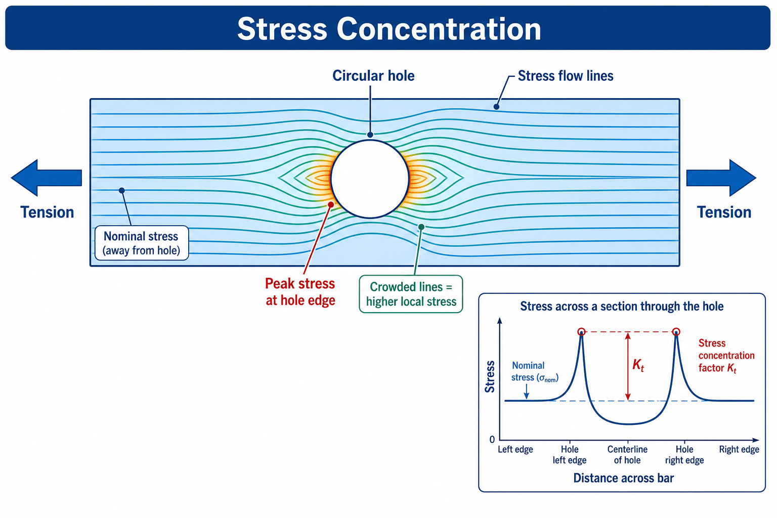
Why it matters. Stress concentrations are the primary sites for fatigue crack initiation, so understanding and minimising them is essential to implant longevity. They explain:
- Plate fractures at screw holes in delayed unions
- Screw breakage at thread roots
- Stem fractures at changes in geometry
- Modular junction failures
History. The concept was first rigorously developed by Inglis (1913) and later expanded by Griffith (1921) in seminal work on fracture mechanics. Inglis showed mathematically that an elliptical hole in a plate concentrates stress at its tips, with the concentration factor depending on the hole's aspect ratio.
The Stress Concentration Factor (Kt)
Definition. The severity of the amplification is quantified by the theoretical stress concentration factor, the ratio of the maximum local stress at the discontinuity to the nominal stress, which is the average stress in the cross-section away from it.
Kt = σ_max local / σ_nominal
At stress risers Kt is typically 3-10. A circular hole has Kt = 3: the stress at its edge is three times the remote stress.
- Kt Value
- Kt = 3
- Clinical Example
- Screw holes in compression plates
- Mitigation
- Use elliptical holes oriented properly
- Kt Value
- Kt = 5-10+
- Clinical Example
- Poorly designed implant corners
- Mitigation
- Add fillet radius to round corners
- Kt Value
- Kt = 1.2-1.5
- Clinical Example
- Well-designed stem tapers
- Mitigation
- Optimise radius for geometry
- Kt Value
- Kt → ∞ (infinite)
- Clinical Example
- Surface defects from manufacturing
- Mitigation
- Polish surfaces, quality control
What sets Kt. Five principles:
- Geometry, not material - Kt depends on shape, not on material properties
- Sharpness - sharp discontinuities have a higher Kt than gradual changes
- Radius - larger fillet radii dramatically reduce Kt
- Orientation - a hole perpendicular to loading has a lower Kt
- Size relative to the component - larger holes relative to component width have a higher Kt
Kt is a geometric property only. A steel plate and a titanium plate with identical geometry have identical Kt values, and a stronger material does not lower it: material choice affects strength and fatigue limit, not the stress concentration factor itself.
Notch sensitivity. Materials do differ in how they respond to a stress concentration, a separate material property called notch sensitivity. The effective (fatigue notch) stress concentration factor, Kf, accounts for it:
Kf = 1 + q(Kt − 1)
The notch sensitivity factor q runs from 0 to 1. At q = 0 the material is insensitive to notches (ductile, wrought alloys); at q = 1 it is fully notch sensitive (brittle materials, cast alloys). Most metals have q = 0.6-0.9, so they partially "feel" the stress concentration.
The Inglis Solution and the Radius of Curvature
The elliptical hole. Everything this topic says about sharpness flows from one equation. For an elliptical hole with semi-axis a perpendicular to the load and semi-axis b parallel to it, Inglis showed the peak stress at the tip is σ_max = σ_nominal × (1 + 2a/b), so:
Kt = 1 + 2(a/b)
An elliptical hole oriented parallel to the load has a lower Kt than a circular one. As b approaches 0 and the hole becomes crack-like, Kt approaches infinity.
The radius-of-curvature form. The tip of the ellipse, the point facing into the load where stress peaks, has a radius of curvature ρ = b²/a. Substituting eliminates b and expresses Kt in terms of the flaw depth a and the tip radius ρ alone:
Kt = 1 + 2√(a/ρ)
This form, which the Inglis analysis makes explicit but which is usually quoted only in its aspect-ratio form, is what governs implant design:
- A circular hole has a = b, so ρ = a and Kt = 1 + 2 = 3: the Kirsch solution for a circular hole in an infinite plate under uniaxial tension, at the hole edge perpendicular to loading
- As the tip radius ρ approaches zero (a crack or sharp scratch), Kt grows without bound, the quantitative basis for saying that a sharp corner has an infinite Kt
- Because Kt scales with the square root of a/ρ, the tip radius dominates: rounding a near-zero notch root to a finite fillet radius collapses Kt far more effectively than shortening the flaw does
In practice. Re-radiusing a thread root or a plate corner is the single highest-yield design lever. A fine machining scratch remains dangerous because its tiny ρ, paired with a small a, still gives a large √(a/ρ). Drilling a rounded "stop hole" at the end of a propagating crack works by the same equation: it replaces a near-zero tip radius with a finite one and drops the local Kt. For a fillet at a shoulder, Kt decreases as the fillet radius increases, and Peterson's charts give the values for specific geometries.
Infinite is a theoretical value. Kt tending to infinity is a property of the linear elastic equations, not of real metal, which yields locally and blunts the tip. A sharp scratch produces a very high stress capped by plasticity rather than an infinite one, and the practical consequence is crack initiation, not immediate failure. That is still why even microscopic surface scratches can initiate fatigue failure.
When a real crack exists. For cracks and sharp notches, Kt is abandoned and the stress-intensity factor K takes over: K = σ√(πa) × Y, where a is crack length and Y a geometry factor, and a critical K determines fracture initiation. Kt governs the elastic stress state at a rounded notch; K governs propagation of a sharp crack. The fatigue-crack process itself (Paris law, crack growth, beach marks) is developed in the fatigue-failure and implant-fracture-biomechanics topics.
Kt = 1 + 2√(a/ρ): the stress concentration at a notch is set by its tip radius ρ, not by the material. Enlarging the fillet radius lowers the peak stress at the notch identically for every alloy, a geometric fix that no increase in yield strength can substitute for. Prevention through design is more effective than using stronger materials, and it is the quantitative reason a well-designed implant in standard titanium alloy outlasts a poorly designed one in high-strength material.
Gross-Section versus Net-Section: Why 'Kt = 3' Is Only the Starting Point
Where the three comes from. Kt = 3 for a circular hole is the Kirsch value for an infinite plate, one very much wider than the hole, and it is referenced to the gross remote stress. Real bone plates are finite in width, and that changes the number.
Gross and net stress. When a hole removes material, the remaining ligament (the net section) carries the whole load over a smaller area, so its nominal stress is higher than the gross:
- Gross nominal: σ_gross = P / (W × t)
- Net nominal: σ_net = P / ((W − d) × t)
Here W is plate width, d hole diameter, t thickness and P the applied load. Kt therefore has two conventions: Ktg references the peak stress to σ_gross and Ktn references the same peak stress to σ_net, related by Ktn = Ktg × (W − d)/W.
As the hole grows. With increasing d/W, the gross-referenced Ktg rises above 3, because the peak stress climbs faster than the gross stress, while the net-referenced Ktn falls towards about 2. For a central hole with d/W of 0.5, Peterson's finite-width charts give a Ktn of roughly 2.1, and hence a Ktg of about 4.2. Only when the hole is very small compared with the width do both converge on the textbook 3.
What it means for a plate. This is why larger holes relative to width raise Kt: the hole concentration and the net-section reduction stack together. An over-drilled hole pushes the true peak stress beyond the nominal three-times figure in the same way, and the fatigue-critical material is the ligament between the hole edge and the plate margin, not the plate as a whole.
Quote Kt = 3 as the idealised circular-hole factor, then qualify it: it assumes the plate is wide compared with the hole and is referenced to gross stress. In a finite-width plate the gross peak-stress factor exceeds 3 and the load is funnelled through the reduced net section, so undersized plates and large or closely spaced holes concentrate stress more than the textbook value implies.
Sources and Severity of Stress Concentrators
Holes. Screw holes in plates are the primary clinical example, with Kt = 3 at the edge of a circular hole. The Kt of an elliptical hole depends on its aspect ratio and orientation.
Notches. A sharp V-notch has a Kt of 5-10, depending on its angle and depth, and a rounded U-notch a lower Kt than a sharp V-notch. Thread roots are notches, sharp or rounded depending on design.
Surface defects. At a crack tip Kt approaches infinity. Surface scratches and machining marks create micro-notches that act as micro-cracks, and corrosion pits create local stress risers.
Corners and transitions. Sharp corners have a theoretically infinite Kt. Abrupt cross-section changes (shoulders) are stress risers, and step transitions are worse than gradual tapers.
Interaction. Multiple stress concentrators in close proximity interact, and the combined Kt may be higher than that of the individual concentrators. Screw holes in series along a plate create multiple stress peaks.
Severity. Stress concentrators grade by Kt:
- Low (Kt less than 2) - generous fillet radii at transitions, polished surfaces without defects, gradual tapers and smooth contours
- Moderate (Kt 2-5) - circular holes, rounded notches, modern rounded thread roots, well-designed modular junctions
- High (Kt greater than 5) - sharp notches and corners, sharp thread roots, cracks and surface defects
Analysis Methods
Analytical solutions. The Kirsch and Inglis solutions cover the circular and elliptical hole. Peterson's Stress Concentration Factors is the standard reference for Kt values for specific geometries, with graphical solutions for holes, notches, shoulders, grooves and fillets that are applicable to orthopaedic implant design optimisation.
Finite element analysis. FEA is the computational method for complex geometries and is used in modern implant design and optimisation. Its peak stress depends on mesh density, so a finer mesh is needed around stress risers for an accurate peak, and mesh convergence studies are required for reliable results.
Experimental methods.
- Strain gauges - measure surface strain near discontinuities
- Photoelasticity - visualises stress distribution in models
- Fatigue testing - determines actual fatigue life under cyclic loading
Design Strategies to Minimise Stress Concentration
Fillet radii. Add generous radii at all corners and transitions: the larger the radius, the lower the Kt. Minimum radius guidelines exist for each geometry type.
Gradual transitions. Avoid abrupt cross-section changes and use tapers rather than steps; optimising the shoulder angle reduces stress peaks.
Surface quality. Polish surfaces to remove micro-defects, use quality control to detect manufacturing scratches, and electropolish critical fatigue areas. Surface treatments such as shot peening improve fatigue resistance.
Holes and load paths. Orient holes and slots optimally relative to the load direction, perpendicular to loading. Design load paths to avoid discontinuities, and redistribute stress around holes with reinforcement; multiple smaller holes may be better than one large hole.
- Mechanism
- Spreads stress over larger area
- Kt Reduction
- 50-80% reduction possible
- Mechanism
- Eliminates abrupt change
- Kt Reduction
- 30-50% reduction
- Mechanism
- Removes micro-notches
- Kt Reduction
- 10-20% improvement in fatigue life
- Mechanism
- Aligns with load direction
- Kt Reduction
- 20-30% reduction
Implant Design Applications
Plates. Screw holes are placed to minimise interaction between stress concentrators, and working length affects the stress distribution across the plate. Locking and compression plates differ in design: threaded locking holes create multiple stress concentrators, and dynamic compression plates may be slightly less prone to fatigue. Modern plates have optimised screw hole geometry (lower Kt), and variable-angle locking reduces stress concentration compared with fixed-angle.
In theatre. An empty screw hole is still a stress concentrator. Bending a plate creates a stress concentration at the bend, and scratches from insertion instruments create surface defects.
Screws. Thread root radius is critical for screw fatigue strength. The thread root acts as a sharp notch, quoted at Kt 3-5, and cyclic loading initiates a fatigue crack there. Modern screws use a rounded V-thread, with the buttress thread superior, and self-tapping and non-self-tapping screws differ in thread geometry.
Thread root geometry is critical for screw fatigue strength. Modern screws use rounded thread roots (fillet radius) rather than sharp V-threads to reduce Kt from 5-10 down to 2-3, dramatically improving fatigue life.
Hip stems. Stem fractures often initiate at geometry changes. The collar-to-stem junction is a stress riser if the transition is abrupt and needs a generous fillet radius, and cross-section changes along the stem should be gradual. The solutions are gradual tapers, polished surfaces and optimised fillet radii; surface finish also affects fretting corrosion at interfaces.
Modular junctions. A Morse taper, such as the head-neck junction, creates a stress concentration at the taper edge. Optimising the taper angle balances stress concentration against impaction force.
Modular hip stems have failed at the neck-body junction due to stress concentration combined with fretting corrosion. The taper geometry concentrates stress at the junction, while micro-motion causes fretting, which accelerates fatigue crack initiation.
Implant Failure from Stress Concentration
How a plate breaks at a screw hole. The sequence runs from normal loading to sudden fracture:
- Normal loading. Bending loads are transmitted through the plate and stress is distributed across its cross-section.
- Stress concentration. At a screw hole the local stress is three times the nominal stress (Kt = 3), highest at the hole edges perpendicular to the plate axis.
- Crack initiation. If the fracture has not healed, after thousands of loading cycles a micro-crack initiates in the high-stress region at the hole edge.
- Propagation. The crack grows incrementally with each cycle (Paris law), and the stress intensity increases as the crack lengthens.
- Sudden fracture. At the critical crack length the remaining cross-section fractures rapidly.
This is why plates fail at screw holes and not between them, and why they break in the setting of delayed union or nonunion.
Screws and stems. Screws break at the thread root, most commonly at the first thread engaged in bone. Stems fracture at geometry transitions such as the collar-stem junction and at modular junctions (head-neck taper), and stem fracture is associated with undersized stems and high-activity patients.
- Location
- Through screw hole
- Mechanism
- Kt = 3, fatigue crack from hole edge
- Location
- Thread root
- Mechanism
- Kt = 3-5, cyclic bending
- Location
- Geometry transition
- Mechanism
- Abrupt change + cyclic loading
Plate fractures in delayed union are not plate defects - they are predictable consequences of stress concentration + cyclic loading. The plate will fail after a predictable number of cycles if the fracture doesn't heal, because stress concentration at screw holes exceeds the fatigue limit.
Reading the fracture surface. Fractography identifies the crack origin at the stress concentrator. Beach marks indicate fatigue crack propagation, and the final rapid fracture zone shows overload failure.
Time to failure. Fatigue life depends on stress amplitude, Kt and the material's fatigue limit. S-N curves (stress against number of cycles) predict cycles to failure at a given stress level, and a higher Kt means a shorter fatigue life at the same nominal stress. The design target is an implant fatigue life greater than the expected healing time multiplied by a safety factor.
How often.
- Plate fracture - under 5% overall with appropriate use; higher in delayed union (15-20%) and nonunion (25-35%); the proximal femur and tibial plateau are high-risk locations
- Screw breakage - under 1% with modern optimised thread design; 2-5% with locking screws in comminuted fractures; usually after partial union with asymmetric loading
- Overall - well-designed implants with proper surgical technique succeed in more than 95%
Differential: Distinguishing Failure Mechanisms
In a viva, the examiner wants you to separate stress concentration, a geometric stress riser, from the mechanisms it is confused with. They overlap, since stress concentration is usually the initiator and fatigue the process, but the discriminators differ.
- Defining feature
- Local elastic stress rise at a geometric discontinuity
- How to tell it apart
- Geometry-dependent, material-independent; an instantaneous stress state
- Typical clinical clue
- Failure originates exactly at a hole, notch, thread root or taper edge
- Defining feature
- Progressive cracking under cyclic load below yield
- How to tell it apart
- Time/cycle-dependent process; needs a crack initiation site (often a stress riser)
- Typical clinical clue
- Beach marks on fractography; failure after weeks-months of loading
- Defining feature
- A pre-existing sharp crack, described by stress intensity factor K
- How to tell it apart
- Use K = Y sigma root(pi a), not Kt, once a real crack exists
- Typical clinical clue
- Manufacturing crack, deep scratch, or propagated fatigue crack
- Defining feature
- Micromotion plus electrochemical attack at an interface
- How to tell it apart
- Needs an interface and motion; surface pitting/oxide debris present
- Typical clinical clue
- Modular taper, plate-screw interface, fretting scars and debris
- Defining feature
- Bone resorption from load bypassing bone via a stiff implant
- How to tell it apart
- A bone remodelling phenomenon, not an implant stress riser
- Typical clinical clue
- Calcar/cortical thinning around a stiff stem, not implant breakage
- Defining feature
- Single supra-physiologic load exceeding strength
- How to tell it apart
- One event, ductile dimpling on fractography, no beach marks
- Typical clinical clue
- Fall or trauma; immediate failure, not cyclic
Clinical Monitoring and Prevention
Surveillance. Serial radiographs follow fracture healing and watch for early implant loosening or hardware prominence; lucency around screws and plate bending are signs of impending failure. Clinical signs of concern:
- New onset of pain at the hardware site
- Swelling or palpable hardware prominence
- Loss of fracture reduction on imaging
Activity. Protected weight-bearing until bony union is achieved, activity restrictions for high-demand patients with large implants, and education about the importance of the fracture-healing timeline.
The healing environment. Biological optimisation (nutrition, smoking cessation), fixation stability adequate for the healing environment, and bone graft augmentation considered in high-risk cases.
Hardware choice. An appropriate plate length and working length, locking plates considered in osteoporotic bone, and no excessive plate bending during contouring.
Prevention of stress concentration failures requires achieving bony union before the implant's fatigue life is exceeded. Focus on optimising the healing environment rather than just relying on stronger implants.
Guidelines, Registries & Global Practice
Standards, Registries and Global Epidemiology
- ISO 7206 (hip stem and neck fatigue), ISO 14242 (THA wear simulation), ISO 14801 (dental/implant fatigue), ASTM F1820 / F2580 (modular taper, neck fatigue) - all mandate cyclic fatigue testing at geometric stress risers
- Regulatory pathways (US FDA 510(k)/PMA, EU MDR CE mark, Australia TGA, Japan PMDA) require a fatigue/stress-concentration design dossier - the requirement is global, not country-specific
- Implant breakage is rare overall but reliably flagged by national joint registries - NJR (UK), AJRR (US), AOANJRR (Australia), SHAR (Sweden), NZJR (New Zealand)
- Modular-neck stems (e.g. recalled large-taper designs) showed elevated revision for fracture/fretting in multiple registries, prompting market withdrawals
- Plate/screw fatigue failure is a recognised mode in nonunion and high-load anatomic sites (distal femur, proximal tibia)
- Plate fracture overall rate is low (a few percent) but rises sharply with delayed/nonunion and high body mass; screw breakage is uncommon with modern rounded thread roots
Related pages: Fatigue Failure is the companion page and the one that completes this one - Kt is an elastic factor, and it is the fatigue notch factor Kf, smaller than Kt by the material's notch sensitivity, that actually governs how long an implant survives; Implant Fracture Biomechanics for the failure event itself and for how working length, screw density and gap size combine; Screw Biomechanics for the hole that is the stress concentrator in almost every construct on this page; Titanium Alloys and Stainless Steel for why the same notch is more dangerous in titanium - it is the more notch-sensitive of the two - and Cobalt-Chrome Alloys for the material that outperformed titanium in the Aljenaei modular-neck testing carded above; Trunnionosis and Taper Corrosion and Corrosion Mechanisms for the fretting-corrosion pathway that turns taper micromotion into crack initiation, which is what the Boettcher and Wodecki cards describe; and Nonunion Management for the clinical situation that causes most plate fatigue failures - the Zhang retrieval broke because the fracture never united, so the implant was cycled indefinitely as the sole load path.
Controversies and Areas of Uncertainty
Locking versus compression plate fatigue. Locking screws add multiple threaded stress concentrators, yet locked constructs can fail more abruptly with little warning. Whether locked or dynamic compression plating is more fatigue-tolerant depends heavily on working length and bridging span: the construct geometry, not the plate type alone, drives peak stress.
Modular necks. Modular neck-stem junctions improve intra-operative versatility but introduce an extra taper stress concentrator vulnerable to fretting fatigue. Several large-taper designs were withdrawn after registry-flagged fractures, and the balance of versatility against added failure risk remains contested.
How predictive is FEA peak stress? At a perfectly sharp corner the FEA peak stress can diverge, as the theory predicts an infinite value. Whether a reported "peak stress" reflects reality or mesh artefact is debated, and fatigue-life prediction often relies on validated notch or critical-distance methods rather than raw peak stress.
Surface treatment durability. Shot peening and electropolishing improve fatigue life by inducing compressive residual stress and removing micro-notches, but the in-vivo durability of these benefits under corrosion and fretting is not fully established.
MCQ Practice Points
Q: What does stress concentration factor (Kt) represent? A: Ratio of local peak stress to nominal stress. Kt = (σ_max local) / (σ_nominal). For circular hole, Kt = 3, meaning stress is 3x higher at hole edge.
Q: What is the stress concentration factor for a circular hole in a plate under tension? A: Kt = 3 - Local stress at hole edge is 3 times the nominal stress in the plate. This is why plates fracture at screw holes.
Q: Why are sharp corners worse than rounded corners for stress concentration? A: Sharp corners have higher Kt values (approaching infinite for perfectly sharp points). Adding fillet radius reduces Kt significantly. Larger radius = lower Kt.
Q: Does using a stronger material reduce stress concentration factor? A: No - Kt is geometry-dependent only. A steel plate and titanium plate with identical geometry have identical Kt. Material selection affects strength and fatigue limit, not Kt itself.
Q: Why do plates typically fracture at screw holes rather than between holes? A: Stress concentration (Kt ≈ 3) at screw holes creates local stress 3x higher than between holes. Fatigue crack initiates where stress is highest.
Exam Viva Scenarios
Practise clinical reasoning and management decisions out loud
“Examiner shows radiograph of fractured plate at screw hole and asks about stress concentration.”
“Examiner: 'You are designing a new hip stem. How would you minimize stress concentration to prevent fatigue fracture?'”
“Examiner: 'A cast cobalt-chrome component and a wrought titanium component have the same notch geometry. Will they fail at the same applied stress? Explain Kt versus Kf.'”
Definition and Kt Factor
- Stress concentration = local stress elevation at geometric discontinuities
- Kt = (local peak stress) / (nominal stress)
- Circular hole: Kt = 3 (stress 3x higher at edge)
- Sharp notch: Kt = 5-10+ (worse than hole)
- Kt is GEOMETRY dependent, NOT material dependent
Common Stress Concentrators
- Holes (screw holes in plates) - Kt ≈ 3
- Sharp corners and notches - Kt = 5-10+
- Thread roots (screws) - Kt = 3-5
- Cracks and scratches - Kt → infinity
- Modular junctions - taper geometry matters
Clinical Failures
- Plate fracture at screw holes (delayed union)
- Screw breakage at thread roots
- Stem fracture at geometry transitions
- All are stress concentration + fatigue
- Prevention: achieve union before fatigue damage
Mitigation Strategies
- Add fillet radii to round corners (larger radius better)
- Avoid sharp edges and abrupt changes
- Polish surfaces to remove micro-defects
- Orient holes perpendicular to loading direction
- Gradual tapers, no steps in geometry
Evidence Base
Peterson's Stress Concentration Factors
- Comprehensive reference for Kt values for virtually all geometric configurations
- Circular hole in plate: Kt = 3 under uniaxial tension
- Sharp notch: Kt = 5-10+ depending on notch angle and depth
- Fillet radius dramatically reduces Kt - charts provided for design optimization
Inglis - Stresses in a Plate Due to the Presence of Cracks and Sharp Corners
- First mathematical analysis of stress concentration around holes and cracks
- Showed elliptical hole concentrates stress at tips: Kt = 1 + 2(a/b)
- As hole approaches crack shape (b→0), Kt approaches infinity
- Foundation for fracture mechanics developed by Griffith
Failure analysis of a locking compression plate with asymmetric holes and polyaxial screws
- Retrieved LCP (AO 32-A1 femoral fracture) failed by fatigue fracture due to nonunion - metallurgy met ASTM standards (not a material defect)
- Fractography: fatigue crack originated at the narrow side of a screw hole; broad side showed final overload crack growth
- FEA: increasing plate working length (distance between innermost screws) lowered peak construct stress
- Maximum stress consistently localised at the screw hole regardless of polyaxial screw angle; -10 degrees gave the most even stress distribution
Long versus short working length distal femoral locking plates (RCT)
- Randomised controlled trial, 61 extra-articular distal femur fractures (long vs short working length titanium LCP)
- Union: 93.3% (long) versus 61.2% (short), p=0.01
- Plate breakage in 3/31 and screw breakage in 2/31 short-working-length cases; zero implant failures in the long-working-length group (p=0.0001)
- Longer working length distributes bending stress over more plate, lowering peak stress at any single screw hole
Modular neck material and assembly method affect fatigue life
- In-vitro testing reproduced the in-vivo modular neck fracture path: distal-lateral neck surface to proximal-medial taper entry (stress concentration at the taper)
- All hand-assembled Ti6Al4V necks failed at 7.0 kN; impact-assembled Ti6Al4V and all CoCrMo necks survived
- Ti6Al4V was more fatigue-susceptible than CoCrMo at the modular junction
- Impact assembly raised both fatigue life and distraction (pull-off) force
Taper junction contamination and assembly reduce junction strength
- Contamination of modular taper (bone/blood), especially with incomplete assembly, increased neck rotation (35.3 vs 2.4 degrees), micromotion (67.8 vs 5.1 micrometres) and axial subsidence (all p less than 0.001)
- Increased micromotion at the taper drives fretting corrosion and accelerates fatigue crack initiation at the stress-concentrating junction
- Need for multiple turns when tightening the locking screw flags intra-operative contamination
- Correct cleaning plus pre-tensioned assembly restored junction strength
Modular neck-stem junction breakage in total hip arthroplasty
- Reported fracture of the female (stem-side) part of a modular neck-stem Morse taper junction
- Risk factors: active, overweight male with a long varus neck (high bending moment at the taper)
- Fretting corrosion plus material fatigue at the added modular interface implicated
- Revision required extended trochanteric osteotomy and a long stem