Thread Geometry | Pullout Strength | Lag Technique | Locking vs Non-Locking
- Pullout strength depends on thread engagement, bone density, and outer diameter
- Lag screw technique achieves compression through threads in far cortex only
- Thread pitch is distance between adjacent threads; lead is axial advance per rotation
- Core diameter determines bending and torsional strength of screw
- Locking screws create fixed-angle construct eliminating screw-plate toggling
- “70% of pullout strength comes from threads engaging outer cortex
- “Stripping torque proportional to outer diameter cubed and bone density
- “Lag screws require gliding hole and thread hole for compression
- “Locking screws function as internal fixator with reduced periosteal compression
Overview
A screw converts rotational torque into axial advancement and fixation force, and it is the fundamental fixation device in orthopaedic surgery. Its biomechanics govern implant selection, insertion technique and construct stability.
Why it matters. Screw pullout or loosening is a common mode of fixation failure, and an understanding of thread engagement, the effect of bone density and screw selection is what prevents it. Lag technique for interfragmentary compression, the choice between locking and non-locking screws, and bicortical versus unicortical fixation all rest on the same principles, and improper technique compromises stability.
Three mechanical modes. Screws function in three mechanical modes, and understanding them is fundamental to screw selection:
- Position screw - holds fragments in the reduced position without compression, its threads engaging both fragments equally
- Lag screw - generates interfragmentary compression, its threads engaging the far fragment only
- Locking screw - its threaded head locks to the plate, creating a fixed-angle construct
Screw Anatomy and Thread Geometry
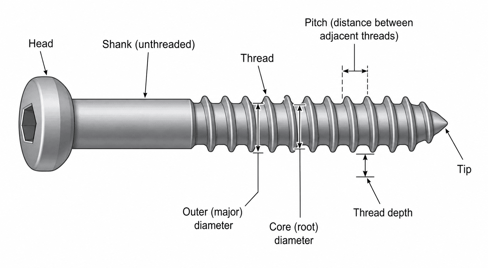
The head. The head transfers torque from the driver to the screw, through a hex, cruciate or star drive, and it is the compression surface, either countersunk or buttress. It may be threaded, as in a locking screw, or smooth, as in a non-locking screw. How it meets a plate defines the screw:
- Conventional (compression) head - smooth, slides in the plate hole and generates compression between plate and bone
- Locking head - threaded to engage the plate, giving a fixed-angle construct
- Variable-angle locking head - allows off-axis insertion and direction adjustment with locking capability
The shank and the threaded length. The shank is the unthreaded portion of the screw. A fully threaded screw has threads along its entire length and acts as a position screw unless a gliding hole is drilled. A partially threaded screw has threads at the tip only, and its smooth shaft glides, which makes it a lag screw by design. A cannulated screw has a hollow core for guidewire placement.
Core diameter sets strength. The core (root) diameter is the diameter at the base of the threads, the smallest diameter of the screw. It determines bending and torsional strength, which depend on the core diameter cubed (moment of inertia). It is also the stress-concentration point during loading, and so the weak point where screws break.
Outer diameter sets pullout. The outer (major) diameter, at the tips of the threads, determines thread contact area and therefore pullout strength and holding power in bone. The trade-off is that a larger outer diameter increases pullout but needs a larger hole, which weakens the bone.
Thread depth. Thread depth is the radial distance from core to outer diameter, (outer - core) / 2. Greater depth increases thread surface area, which is why cancellous screws have deeper threads for trabecular engagement. Threads that are too deep reduce core strength.
Thread angle. The angle between the thread flank and the perpendicular to the screw axis is typically 40-60 degrees, the optimal range. A smaller angle increases stripping resistance; a larger angle makes insertion easier but lowers holding power.
Pitch and lead. Examiners frequently test this distinction. Pitch is the distance between adjacent threads, measured parallel to the axis: a smaller pitch puts more threads in a given length and gives greater holding power. Lead is the axial distance the screw advances in one complete rotation:
- Single-lead (most common) - lead equals pitch
- Dual-lead - two helical thread paths, so lead is twice the pitch, giving faster insertion with less rotation
- Triple-lead - lead is three times the pitch
Thread forms. Three thread profiles are named:
- V-thread - standard, with good general properties
- Buttress thread - asymmetric, with better axial pullout resistance
- Hi-Low thread - variable thread depth, combining cortical and cancellous properties
The tip. Self-tapping screws cut their own threads; non-self-tapping screws need the hole tapped first. Tips may be self-drilling, trocar (sharp) or blunt.
Over-tapping creates threads too large for the screw and reduces thread engagement, which decreases pullout strength and risks early failure. Use the tap size that matches the screw.
Materials. Screws are made from three groups of material:
- Stainless steel - high strength, corrosion resistant
- Titanium - biocompatible, with a lower modulus and reduced stress shielding
- Bioabsorbable (PLLA/PGA) - used in low-stress applications
Named designs. Some screws are known by name or by site:
- Herbert screw - headless, variable pitch, buried fixation
- Syndesmotic screw - crosses the tibiofibular syndesmosis
- Pedicle screw - a large cancellous screw for spine fixation
Pullout Strength and Failure Mechanisms
Pullout strength is the force required to extract a screw from bone, and its loss is the primary mode of fixation failure in many constructs. It depends on the screw and on the bone, and understanding both is what allows fixation strength to be optimised.
Screw factors. Outer diameter is the most important screw factor. Pullout force is proportional to it, doubling the diameter approximately doubles pullout strength, and thread surface area increases with it. Thread engagement length has a linear relationship with pullout strength, and a minimum of 3-4 threads is required for adequate purchase. Thread geometry adds the rest: depth increases surface area, angle affects stripping resistance, and pitch sets the number of engaged threads per unit length.
Bone factors. Bone density is the most important bone factor, and pullout strength is proportional to BMD. Cortical bone is 3-4 times stronger than cancellous, and osteoporotic bone reduces pullout strength by 50-70%, with the loss already under way in osteopenic bone:
- Expected Pullout Strength
- 100% baseline
- Optimisation Strategy
- Standard technique adequate
- Expected Pullout Strength
- 70-85% of normal
- Optimisation Strategy
- Consider locking screws, bicortical fixation
- Expected Pullout Strength
- 30-50% of normal
- Optimisation Strategy
- Locking screws, cement augmentation, longer constructs
Where the threads engage. In bicortical fixation the outer cortex provides 70% of pullout strength and the far cortex adds 30%, so near-cortex engagement is critical.
Pullout failure. A screw pulls out of bone in one of three ways:
- Interface failure, the most common. The threads shear through bone when the bone is weaker than the screw-bone interface, typically in osteoporotic or cancellous bone. A larger diameter, longer engagement or cement augmentation prevents it.
- Bone fracture. The cylinder of bone around the screw fractures, with oversized screws or poor technique, and the permanent damage reduces the strength of any re-fixation. Proper hole size and avoiding over-tightening prevent it.
- Screw deformation. The threads deform under excessive load. This is rare in modern screws with adequate material strength but may occur with cyclic loading and fatigue, and an adequate screw size for the expected loads prevents it.
Stripping and pullout both lose fixation, at different stages. Stripping happens during insertion, when insertion torque exceeds bone strength: the threads are created and stripped immediately, and it is a technique error. Pullout happens after insertion, when axial load exceeds the strength of the thread-bone interface, and it is a load or bone-quality problem. Breakage is fatigue under cyclic bending and torsional loads. Recognising the mechanism guides prevention and revision.
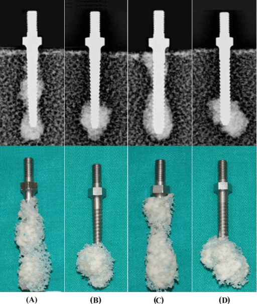
Enhancing pullout. There are two routes, modifying the screw and augmenting the bone, and in challenging bone they can be combined.
- Mechanism
- Increases thread contact area
- Benefit
- 30-50% strength increase per mm
- Application
- When bone stock adequate
- Mechanism
- Engages far cortex (adds 30%)
- Benefit
- 2-3x unicortical strength
- Application
- When length permits safe passage
- Mechanism
- More threads engaged
- Benefit
- Linear increase in strength
- Application
- Minimum 8-10mm engagement recommended
- Mechanism
- Compression with insertion
- Benefit
- Dynamic compression effect
- Application
- Headless compression screws
- Indication
- Severe osteoporosis, revision
- Mechanism
- Fills voids, increases contact
- Evidence
- 70-100% strength increase
- Indication
- Metaphyseal voids, mild osteoporosis
- Mechanism
- Remodels to bone over time
- Evidence
- 40-60% strength increase, bioresorbable
- Indication
- Osteoporotic bone, comminution
- Mechanism
- Angular stability, load sharing with plate
- Evidence
- Reduces dependence on pullout strength
Cortical versus Cancellous Screws
Screw design optimised for the bone type improves fixation strength and reduces complications.
- Cortical Screw
- Fine (1.0-1.5 mm)
- Cancellous Screw
- Coarse (2.5-3.0 mm)
- Cortical Screw
- Shallow (0.5 mm)
- Cancellous Screw
- Deep (1.0-1.5 mm)
- Cortical Screw
- 70-80% of outer diameter
- Cancellous Screw
- 50-60% of outer diameter
- Cortical Screw
- High (7-10)
- Cancellous Screw
- Low (3-4)
- Cortical Screw
- Cortical bone, diaphyses, plates
- Cancellous Screw
- Cancellous bone, metaphyses, epiphyses
- Cortical Screw
- Higher in cortical bone
- Cancellous Screw
- Lower but adequate in trabecular bone
- Cortical Screw
- Higher (requires tapping often)
- Cancellous Screw
- Lower (usually self-tapping)
The cortical screw. Dense cortical bone gives high pullout strength per thread, so the cortical screw uses a fine pitch to maximise the number of engaged threads, and its high thread count spreads force over more of the bone-screw interface. Shallow threads keep the core diameter large, so the high core-to-outer ratio buys a stronger core. The 3.5mm and 4.5mm cortical screws used for plate fixation are the examples.
The cancellous screw. Trabecular bone needs a larger thread area for equivalent strength. The coarse pitch allows deeper penetration into trabecular bone, the wider thread spacing engages more trabeculae per thread, and deep threads increase thread surface area in porous bone. The price is the core: a cancellous screw has a larger outer diameter for pullout but a smaller core, and so less bending strength. The 6.5mm and 7.3mm cancellous screws for metaphyseal fixation are the examples.
A cortical screw in cancellous bone gives inadequate thread engagement: the fine threads sit between the trabeculae without engaging them. A cancellous screw in cortical bone is difficult to insert, because the coarse threads need high torque and the large core reduces penetration. Match the screw design to the bone.
Lag Screw Biomechanics and Technique
Lag screws generate interfragmentary compression, and they are the gold standard for fracture fixation when anatomic reduction and absolute stability are desired.
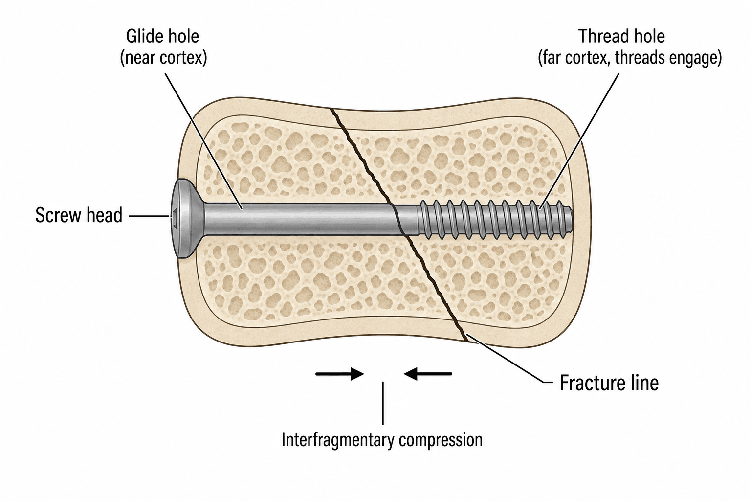
The principle. A lag screw achieves compression by engaging its threads in the far cortex or fragment only, while the shaft glides freely through the near cortex or fragment. As it is tightened, the head contacts the near fragment and the threads pull the far fragment towards it. Continued tightening increases the compression force, friction at the fracture site provides stability, and rotational torque has been converted into compressive force across the fracture.
Two holes make it work. Each has its own diameter:
- Gliding hole in the near cortex or fragment, of a diameter equal to or slightly larger than the screw's outer diameter, so the shaft passes with no thread engagement and no purchase
- Thread hole in the far cortex or fragment, of a diameter equal to the core diameter, so the threads cut into bone during insertion and provide the purchase for compression
A screw only functions as a lag screw if a gliding hole is created. Without one, the threads engage both fragments equally and it becomes a position screw, which prevents compression. This is the most tested concept about lag screws, and examiners often ask what happens if you forget the gliding hole.
Lag Screw Insertion Sequence
Achieve and maintain anatomic reduction with clamps or provisional fixation. Gap closure is critical before lag screw insertion.
Drill the near cortex or fragment with the gliding hole drill, perpendicular to the fracture plane for the optimal compression vector.
Through the gliding hole, drill the far cortex or fragment with the thread hole drill. Measure depth for screw length selection.
Tap the thread hole if using a non-self-tapping screw; self-tapping screws cut their own threads. Tapping reduces insertion torque and heat generation.
Countersink if needed. Insert the screw with gradual tightening: the shaft glides through the near cortex, the threads engage the far cortex only, and the head compresses the near fragment.
Tighten until adequate compression is achieved. Avoid over-tightening, which strips threads or fractures bone. Assess that the reduction is maintained.
Excessive compression can fracture osteoporotic bone or comminute butterfly fragments. Titrate compression force to bone quality, and in very osteoporotic bone consider a washer under the screw head to distribute the load.
Lag by design or by technique. Both achieve interfragmentary compression through the same principle.
- Mechanism
- Standard screw + gliding hole
- Advantages
- Any screw can be used, flexible application
- Disadvantages
- Requires drilling two different holes, technique dependent
- Mechanism
- Partially threaded screw (smooth shaft)
- Advantages
- Shaft automatically glides, simpler technique
- Disadvantages
- Less versatile, must match fragment thickness to thread length
A lag screw by design is partially threaded, smooth proximally and threaded distally. It needs a single drill hole of thread-hole size, but its smooth shaft must be longer than the near fragment is thick, and its threads long enough to engage the far fragment. The 6.5mm and 7.3mm cannulated screws are common examples.
A lag screw by technique is a fully threaded screw with a deliberate gliding hole. It is more versatile, since any screw can be used as a lag screw, and it allows precise control of where the compression goes.
Testing and Imaging Screw Fixation
Mechanical testing. Screw performance in the laboratory is measured by a small set of tests:
- Pullout testing - axial load to failure, measuring the strength of the screw-bone interface
- Insertion torque - resistance during insertion, which correlates with pullout; higher torque suggests better bone engagement
- Stripping torque - maximum torque before thread failure
- Four-point bending - screw strength
- Fatigue testing - cyclic loading to assess long-term performance
What the tests report. Stiffness is the force/displacement ratio before failure, ultimate load the maximum force before the construct fails, and energy to failure the area under the load-displacement curve. Finite element analysis models stress distribution, and predictive modelling simulates optimal screw placement.
Bone quality. DEXA measures bone mineral density, which affects pullout strength; quantitative CT gives volumetric density for planning a screw trajectory, and intraoperative insertion torque serves as a surrogate for bone quality.
Imaging the construct. Each modality answers a different question:
- Plain radiographs - screw position, backing out, lucency around the threads
- CT - detailed assessment of screw purchase and cortical breach
- Fluoroscopy - intraoperative confirmation of trajectory and depth
Screw Selection
Screw selection depends on fracture pattern, bone quality, fixation goals and anatomic location.
Compression or bridging. There are two fundamental strategies. Absolute stability with compression (lag screws, compression plates) suits simple fractures with good bone contact. Relative stability with bridging (locked plates, external fixators) suits comminuted fractures or osteoporotic bone. Screw choice follows the strategy: lag screws, partially threaded or by technique, for compression; locking or position screws for bridging; and locking plate-screw constructs where angular stability is needed.
Matching the bone. Use cortical screws in cortical bone, with bicortical purchase when possible, and cancellous screws in cancellous bone, maximising thread engagement. In osteoporotic bone, use locking screws and consider augmentation.
Screw length. Measure depth accurately with the depth gauge. Go bicortical when strength is needed, and avoid excessive protrusion, which irritates soft tissue.
- Optimal Screw Choice
- Cortical lag screw through plate
- Rationale
- Compression with adequate pullout strength in cortical bone
- Optimal Screw Choice
- Locking screws, bridge plate
- Rationale
- Angular stability without compression of fragments
- Optimal Screw Choice
- Locking screws with cement augmentation
- Rationale
- Fixed-angle support with enhanced pullout in weak bone
- Optimal Screw Choice
- Partially threaded cancellous lag screw
- Rationale
- Maximum compression with lag by design
- Optimal Screw Choice
- Locking screws, bypass fixation
- Rationale
- Avoid stress risers near prosthesis, maintain stability
- Optimal Screw Choice
- Smooth pins or small cortical screws
- Rationale
- Avoid crossing physis, adequate strength in young bone
Osteoporotic bone. Conventional screws rely on friction between plate and bone, which fails in weak bone, whereas locking screws reduce the reliance on bone quality through angular stability. The strategy:
- Prefer locking screws for angular stability
- Consider cement augmentation for critical screws
- Maximise screw length and bicortical purchase
- Avoid compression, which risks fragmentation
- Use plates with greater working length to distribute stress
High-energy trauma. In high-energy injuries the strategy is:
- Bridge plating to preserve soft tissue and biology
- Locking screws for angular stability across the comminution
- Minimise periosteal stripping, using locked plates as internal fixators
- Consider lag screws for the main fragments only
- Leave the comminuted zone unfixed to allow callus formation
- Solution
- Locking screws
- Mechanism
- Angular stability independent of bone-screw interface
- Solution
- Larger diameter screw
- Mechanism
- Fresh thread engagement
- Solution
- Cement augmentation
- Mechanism
- Increases pullout by 100-200%
- Solution
- Unicortical locking screws
- Mechanism
- Fixed-angle without far cortex needed
Working length is the main stiffness dial. Omitting one screw hole either side of the fracture makes the construct roughly twice as flexible in both compression and torsion. More than three screws per fragment adds little axial stiffness, and keeping the plate close to the bone matters, because increasing the plate-to-bone distance reduces construct stability.
The rule differs by fracture pattern, and this catches people out. In a simple fracture with a small gap and cortical contact, deliberately omit one or two holes each side to allow the micromotion that produces callus. In a comminuted fracture with a large gap and no bone contact, place the innermost screws as close as practicable to the fracture: a long working length without cortical contact failed earlier under dynamic loading.
Screw spacing. Avoid clustering screws, which concentrates stress, and maintain adequate bone bridges between them.
Headless Compression Screws and the Differential-Pitch Principle
A headless compression screw is buried entirely beneath the articular or cortical surface, so it can cross a joint surface or fix a small bone with no prominent head to impinge. How a screw with no head generates compression is a recurring basic-science viva question.
Differential pitch. The leading (far) threads are coarser than the trailing (near) threads, so they advance further per turn. As the screw is driven, the far fragment is pulled towards the near fragment and the gap closes, producing compression along the screw without any head pressing on the cortex.
- Lag (headed) screw
- Screw head pressing the near fragment while threads pull the far fragment (needs a gliding hole)
- Headless differential-pitch screw
- Coarser leading threads advance the far fragment faster than the finer trailing threads, drawing the fragments together
- Lag (headed) screw
- Prominent head must seat on or in the cortex
- Headless differential-pitch screw
- Buried below the articular/cortical surface (headless) - no impingement
- Lag (headed) screw
- Diaphyseal/metaphyseal fragments where a head can sit
- Headless differential-pitch screw
- Small-bone and intra-articular fixation (scaphoid, osteochondral fragments, small-joint arthrodesis)
- Lag (headed) screw
- Titrated by the surgeon's feel on the head
- Headless differential-pitch screw
- Largely fixed by the design; both thread zones must gain purchase
Cannulated Screw Biomechanics
A cannulated screw has a hollow axial core so that it can be railed over a pre-placed guidewire. That gives accurate, reproducible and percutaneous placement where the trajectory is critical: the femoral neck, scaphoid, SCFE and sacroiliac joint.
The strength cost is small. The hollow core does reduce bending, torsional and fatigue strength relative to a solid screw of the same outer diameter, but the penalty is modest. Bending stiffness rises steeply with radius, with the fourth power, and the central core is the lowest-stressed material, so removing it costs relatively little. Pullout, a thread-bone property, is essentially preserved.
In practice. Manufacturers often make cannulated designs a touch larger in diameter to offset the difference. The practical cautions are guidewire bending, inadvertent advancement, and breakage during drilling.
- Solid screw
- Free-hand trajectory
- Cannulated screw
- Passed over a pre-placed guidewire - accurate, reproducible, percutaneous
- Solid screw
- Higher for a given outer diameter
- Cannulated screw
- Slightly reduced (central core removed), but the penalty is modest
- Solid screw
- Set by outer diameter and thread engagement
- Cannulated screw
- Essentially preserved (pullout is a thread-bone property, not a core property)
- Solid screw
- General fixation
- Cannulated screw
- Trajectory-critical or percutaneous fixation (femoral neck, scaphoid, SCFE, sacroiliac)
Locking versus Non-Locking Screws
Locking screw technology revolutionised fracture fixation by creating fixed-angle constructs with angular stability.
How locking works. The screw head has threads that engage matching threads in the plate hole, fixing the angle between screw and plate, typically perpendicular. The screw cannot toggle or back out, and load passes through the screw-plate interface rather than through friction.
The internal fixator. A locked plate spans the fracture without compressing the periosteum and needs no contact with bone. It works as an internal fixator, and its biomechanics are fundamentally different from those of a conventional construct.
- Non-Locking
- Friction (compression)
- Locking
- Thread engagement (fixed)
- Non-Locking
- No (screw can toggle)
- Locking
- Yes (fixed angle)
- Non-Locking
- Required (friction)
- Locking
- Not required (bridge)
- Non-Locking
- Yes (may devascularise)
- Locking
- No (preserves perfusion)
- Non-Locking
- High (relies on pullout)
- Locking
- Lower (angular stability)
- Non-Locking
- Tolerant of angle variation
- Locking
- Requires precise perpendicular insertion
When to lock. Locking screws have the advantage in:
- Osteoporotic bone - angular stability reduces reliance on pullout strength
- Comminuted fractures - bridge plating without compressing the fragments
- Periarticular fractures - fixed-angle support for subchondral bone
- Periprosthetic fractures - avoid stress shielding while providing stability
- Minimally invasive plating - preserves soft tissue and periosteal blood supply
When not to. Conventional screws keep advantages of their own:
- Compression - interfragmentary compression with lag technique
- Correction - the screw angle can be adjusted to correct alignment during insertion
- Bone contact - plate-bone friction provides additional stability
- Simple fractures - adequate fixation at lower cost
- Revision - easier to remove if needed
Hybrid constructs. Combining the two brings the best of both technologies to complex fracture patterns: lag screws through the plate compress the main fragments, and locking screws in the metaphyseal regions give angular stability.
Locking screws lock the fracture in whatever position exists when they are tightened. Conventional screws can be used to manipulate the reduction; locking screws cannot, and they preserve a malreduction. Achieve perfect reduction BEFORE inserting locking screws, with provisional fixation and intraoperative imaging. A common exam question.
Locking-specific complications. Locking brings failure modes of its own:
- Cross-threading - the screw threads misalign with the plate threads when insertion is not perpendicular, losing the locking mechanism and angular stability and weakening the construct. Prevented with the drill guide, a perpendicular approach and visual confirmation.
- Cold welding - titanium screw threads gall titanium plate threads, with excessive insertion torque or cyclic loading, making removal difficult or impossible. Avoid over-tightening.
- Stress concentration - the fixed-angle construct concentrates stress at the screw-bone interface, more than toggling non-locking screws do, and can cause screw cutout in osteoporotic bone. Use adequate screw length and consider cement augmentation.
Locking screws can be difficult to remove because of cold welding, cross-threading damage or bone ingrowth into the threads. Plan for potential explant at the index surgery and have an extraction set available at removal. Consider a titanium plate with stainless steel screws to reduce the risk of cold welding.
Surgical Technique
Standard insertion. Four steps:
- Drill the pilot hole with the drill bit appropriate to the screw's core diameter
- Measure depth with the depth gauge
- Tap the hole if the screw is not self-tapping
- Insert the screw to the appropriate torque
Locking screws. Ensure the plate is properly seated before drilling, and use the threaded drill guide to hold the trajectory. Drill bicortically when possible, although unicortical purchase is adequate with locking. Do not over-torque, because cross-threading damages the mechanism.
Cannulated screws. Placement follows the guidewire:
- Place the guidewire under fluoroscopy
- Confirm its position in two planes
- Drill over the wire, protecting it from spinning
- Insert the screw, and remove the wire once the screw is seated
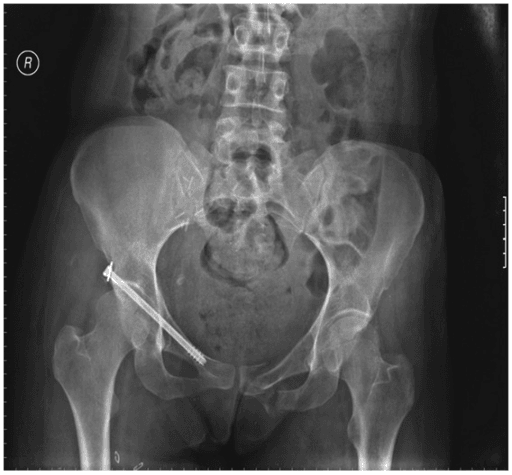
Cement augmentation. The cement goes in before the screw:
- Create a slightly undersized pilot hole
- Inject low-viscosity cement into the hole, through a fenestrated screw or by syringe
- Insert the screw into the cement before polymerisation
- Hold until the cement sets, 2-3 minutes
Complications
Thread stripping. Stripping occurs when insertion torque exceeds the bone's capacity for purchase, and it is more common in osteoporotic bone. Stop at the appropriate torque, when increased resistance is felt at final seating, and avoid overtightening. The salvage is a larger-diameter screw, cement augmentation or an alternative fixation point.
Screw pullout. Purchase is lost when cyclic loading exceeds pullout strength. Osteoporosis, unicortical fixation and short screws are the risk factors; maximising thread engagement, bicortical fixation, locking screws and cement prevent it.
Screw breakage. Screws fail by fatigue under cyclic loading at stress-concentration points, the thread-shaft junction. Delayed union, a high activity level and inadequate construct stability are the risk factors, and adequate construct stability, bridging long segments, prevents it.
Hardware prominence. A screw that is too long or at the wrong angle causes soft-tissue irritation and tendon damage. Accurate measurement and fluoroscopic confirmation prevent it.
Stress shielding. When a rigid construct carries the load, the bone does not remodel normally. It is more common with stiff locking constructs, and plate removal after healing can be considered.
Thermal necrosis. Drilling without irrigation generates heat greater than 47°C, causing bone necrosis and screw loosening. Sharp drill bits, irrigation and intermittent drilling prevent it.
Infection at screw sites. Biofilm forms on the implant surface, and stainless steel is more resistant to adhesion than titanium. Management is debridement, with implant exchange if the implant is loose.
Reading the failing construct. A radiograph showing a problematic screw is a classic viva and CIM scenario, and distinguishing the mode of failure dictates the salvage strategy.
- Typical Radiographic Sign
- Peri-screw lucency (halo) more than 2mm, often progressive
- Underlying Mechanism
- Cyclic micromotion exceeding interface tolerance; poor bone quality
- Salvage / Action
- Assess union and stability; revise to larger/locking screws or augment
- Typical Radiographic Sign
- Screw head proud of plate, increasing screw protrusion on serial films
- Underlying Mechanism
- Axial load exceeding thread purchase; inadequate initial bicortical engagement
- Salvage / Action
- Longer or bicortical screws, locking construct, cement augmentation
- Typical Radiographic Sign
- Discontinuity of screw, usually at thread-shaft junction or empty plate hole
- Underlying Mechanism
- Cyclic loading at a stress riser, frequently signalling delayed/nonunion
- Salvage / Action
- Investigate for nonunion; revise construct and address biology
- Typical Radiographic Sign
- Screw migration through subchondral bone into joint
- Underlying Mechanism
- Collapse at metaphysis in osteoporotic bone; tip-apex distance too great
- Salvage / Action
- Revision fixation, augmentation, or arthroplasty depending on joint
- Typical Radiographic Sign
- Intact screw that will not disengage at removal
- Underlying Mechanism
- Galling of titanium screw head against titanium plate threads
- Salvage / Action
- Conical extraction set, plate-cutting, or carbide burr removal
Postoperative Care
Weight-bearing. Progression is based on construct stability, fracture pattern and bone quality. Locking constructs may allow earlier weight-bearing in osteoporotic bone, whereas lag screw fixation requires protected weight-bearing until healing.
- Initial Weight-Bearing
- Touch weight-bearing 6-8 weeks
- Rationale
- Compression depends on bone contact
- Initial Weight-Bearing
- Partial weight-bearing 4-6 weeks
- Rationale
- Plate protects lag screws
- Initial Weight-Bearing
- Weight-bearing as tolerated (if stable)
- Rationale
- Angular stability distributes load
- Initial Weight-Bearing
- Based on weakest component
- Rationale
- Conventional screws may limit early loading
Follow-up. Serial radiographs assess fracture healing and implant position, watching for screw loosening (lucency around the threads), migration or breakage. Clinically, look for screw prominence causing soft-tissue irritation, signs of loosening or migration, and symptoms suggesting hardware failure. Screw back-out suggests inadequate initial purchase or excessive motion at the fracture site, and broken hardware indicates fatigue failure, from nonunion or construct insufficiency, and should prompt investigation for nonunion.
Activity. Restrict high-impact activities during the healing phase, and progress gradually on radiographic and clinical progress, taking account of age, bone quality and compliance.
Hardware removal. Removal is not routine in adults unless the hardware is symptomatic. Consider it in young patients with forearm plates, because of the refracture risk. It is typically done 12-24 months after complete healing.
Outcomes
What decides success. Beyond bone quality, fixation success depends on surgical technique (proper drilling, tapping and insertion torque), construct design (appropriate screw selection for the application) and patient factors (compliance, comorbidities and smoking status).
Union rates. By fixation type:
- Lag screw fixation - 90-95% union for simple fractures
- Conventional plate fixation - 85-95%, depending on fracture pattern
- Locking plate fixation - similar union rates, advantageous in osteoporotic bone
Locking versus conventional. Meta-analyses show equivalent union rates in normal bone, and locking constructs are superior in osteoporotic metaphyseal fractures. Cost-effectiveness favours conventional screws when bone quality is adequate.
Hardware removal rates. Overall, symptomatic hardware runs at 5-15%, higher in subcutaneous locations such as the ankle, wrist and clavicle. Locking screws may be harder to remove.
Timing of failure. Early failure, in less than 6 weeks, usually reflects a technical error or an inadequate construct. Late failure, after 6 weeks, suggests nonunion or fatigue from excessive motion. Screw breakage indicates stress concentration and cyclic loading beyond the fatigue limit.
Guidelines, Registries & Global Practice
Why Screw Biomechanics Matters Globally
Internal fixation with screws is among the most frequently performed orthopaedic interventions worldwide, and the burden is rising with an ageing, increasingly osteoporotic population. Fragility fractures of the hip, pelvis, distal radius, proximal humerus and ankle dominate the elderly trauma workload, and these are precisely the metaphyseal, low-density sites where screw purchase is most marginal and where locking and augmentation strategies are most often required.
Population drivers of fixation difficulty
- Fall-related fractures are increasing across most adult age ranges, not only the very elderly, with the steepest relative rises in younger women and in men over 80. [1]
- Osteopenic bone already reduces screw pullout strength to roughly three-quarters of normal, so the at-risk population extends well beyond those with established osteoporosis. [2]
- Bone mineral density is the single most important patient determinant of screw holding power across cortical, cancellous and pedicle screw studies. [2]
Because the underlying physics of thread engagement, compression and angular stability are universal, screw biomechanics is examined in essentially identical form across fellowship boards worldwide.
References
- Court-Brown CM, Clement ND, Duckworth AD, Biant LC, McQueen MM. The changing epidemiology of fall-related fractures in adults. Injury. 2017;48(4):819-824. doi:10.1016/j.injury.2017.02.021
- Lee SJ, Lee JH, Lee HJ, Oh JW, Park IH. Pullout strength of pedicle screws using cadaveric vertebrae with or without artificial demineralization. Spine J. 2021;21(9):1580-1586. doi:10.1016/j.spinee.2021.04.010
- Yerby S, Scott CC, Evans NJ, Messing KL, Carter DR. Effect of cutting flute design on cortical bone screw insertion torque and pullout strength. J Orthop Trauma. 2001;15(3):216-221. doi:10.1097/00005131-200103000-00012
- Stoffel K, Dieter U, Stachowiak G, Gachter A, Kuster MS. Biomechanical testing of the LCP - how can stability in locked internal fixators be controlled? Injury. 2003;34(Suppl 2):B11-19. doi:10.1016/j.injury.2003.09.021
- Perren SM. Evolution of the internal fixation of long bone fractures. The scientific basis of biological internal fixation. J Bone Joint Surg Br. 2002;84(8):1093-1110. doi:10.1302/0301-620X.84B8.13752
- Konig A, Oberkircher L, Beeres FJP, Babst R, Ruchholtz S, Link BC. Cement augmentation of sacroiliac screws in fragility fractures of the pelvic ring. Injury. 2019;50(8):1411-1417. doi:10.1016/j.injury.2019.06.025
- Schatzker J, Sanderson R, Murnaghan JP. The holding power of orthopedic screws in vivo. Clin Orthop Relat Res. 1975;(108):115-126. doi:10.1097/00003086-197505000-00019
MCQ Practice Points
Q: What are the key design parameters of a screw that affect its holding power?
A: (1) Outer diameter: Larger = more bone contact, greater pullout resistance. (2) Root diameter (core): Determines bending/torsional strength. (3) Pitch: Distance between threads; smaller pitch = more threads per unit length. (4) Thread depth: Outer minus root diameter; deeper = more purchase. (5) Thread profile: Buttress, V-thread, asymmetric designs. Pullout strength proportional to thread depth × thread length × bone density.
Q: What is the difference between cortical and cancellous screws?
A: Cortical screws: Smaller pitch (more threads/cm), smaller thread depth, fully threaded, designed for dense cortical bone. Cancellous screws: Larger pitch, deeper threads, often partially threaded, designed for trabecular bone. Cancellous screws have larger outer:core ratio for better purchase in soft bone. Partially threaded cancellous screws allow lag effect.
Q: What is the mechanism of lag screw fixation?
A: Lag technique creates interfragmentary compression. Mechanism: Threads engage only the far cortex (glide hole in near cortex), as screw is tightened, the head compresses fragments together. Can be achieved with: (1) Partially threaded screw (thread length shorter than fracture gap), or (2) Fully threaded screw with overdrilled glide hole. Compression generates friction resistance to shear.
Q: What is the relationship between screw insertion torque and pullout strength?
A: Insertion torque does NOT equal pullout strength. Insertion torque: Rotational force to advance screw (friction-dependent). Pullout strength: Axial force to extract screw (thread engagement in bone). Overtightening (excessive torque) can strip threads, reducing pullout strength. Optimal insertion: "Hand-tight" feel. Self-tapping screws have lower insertion torque than non-self-tapping.
Q: How do locking screws differ from conventional screws biomechanically?
A: Conventional screws: Compression between plate and bone, friction-based stability, pullout depends on bone quality, toggle under load. Locking screws: Threaded head locks to plate (fixed-angle construct), load shared across all screws, no plate-bone compression needed, better in osteoporotic bone. Locking construct acts as internal fixator. Disadvantage: Cannot achieve interfragmentary compression.
Basic Science Viva Scenarios
Practise clinical reasoning and management decisions out loud
“Explain the factors that determine screw pullout strength and how you would optimize fixation in osteoporotic bone.”
“You are fixing a simple oblique diaphyseal fracture. Explain the biomechanical principle of lag screw technique and describe how to achieve compression with a fully threaded screw.”
“Compare the biomechanics of locking and non-locking screws. When would you choose each type and what are the potential complications of locking screws?”
Screw Anatomy
- Core diameter: determines bending and torsional strength
- Outer diameter: determines pullout strength (thread contact area)
- Pitch: distance between threads (1.0-1.5mm cortical, 2.5-3.0mm cancellous)
- Lead: axial advance per rotation (equals pitch for single-lead screws)
- Thread depth: (outer - core diameter) / 2 (shallow cortical, deep cancellous)
Pullout Strength Factors
- Outer diameter (most important screw factor) - proportional to thread area
- Thread engagement length - linear relationship with pullout force
- 70% from outer cortex, 30% from far cortex (bicortical fixation)
- Bone density (most important bone factor) - cortical 3-4x cancellous
- Bicortical fixation: 2-3x strength of unicortical
- Osteoporotic bone: 50-70% reduction in pullout strength
Lag Screw Principle
- Compression via threads engaging far cortex only
- Gliding hole (near cortex): diameter = screw outer diameter
- Thread hole (far cortex): diameter = screw core diameter
- No gliding hole = no compression (becomes position screw)
- Lag by design: partially threaded screw (smooth shaft glides)
- Lag by technique: fully threaded screw with deliberate gliding hole
Cortical vs Cancellous Screws
- Cortical: fine pitch (1.0-1.5mm), shallow threads, 70-80% core/outer ratio
- Cancellous: coarse pitch (2.5-3.0mm), deep threads, 50-60% core/outer ratio
- Cortical: diaphyseal, plate fixation, high pullout in dense bone
- Cancellous: metaphyseal, epiphyseal, deep threads engage trabeculae
- Wrong type = poor fixation (cortical in cancellous, cancellous in cortical)
Locking vs Non-Locking
- Non-locking: friction-based, screw toggles, plate-bone compression
- Locking: threaded head-plate interface, fixed angle, angular stability
- Locking advantages: osteoporotic bone, comminution, periosteum preservation
- Locking complications: cross-threading, cold welding, locks malreduction
- Non-locking advantages: compression (lag), angle adjustment, cost
- Achieve perfect reduction BEFORE locking screws (cannot adjust after)
Clinical Applications
- Simple fracture, good bone: non-locking with lag compression
- Comminuted metaphyseal: locking screws, bridge plating
- Osteoporotic periarticular: locking screws with cement augmentation
- Periprosthetic: locking screws, bypass fixation
- Hybrid constructs: lag screws for main fragments, locking for metaphyses
- Bicortical when safe: 2-3x strength, need 3-4 threads beyond far cortex
Evidence Base
The Holding Power of Orthopaedic Screws In Vivo
- Classic in vivo push-out study of screws implanted for 3 months in a canine model
- Self-tapping and non-self-tapping screws of similar material and size maintained comparable holding power at all intervals tested
- Largest screw (4.5mm AO cortical) provided the greatest safety factor against push-out in the unloaded system
- No histological evidence that self-tapping insertion caused bone necrosis or fibrous-tissue loss of purchase
Pullout Strength of Pedicle Screws and Bone Mineral Density
- Five lumbar and five thoracic vertebrae from a SINGLE cadaver, each split into paired hemivertebrae - 20 pedicles in total - comparing normal against artificially demineralised (osteopenic) bone
- Mean pullout strength of the osteopenic model was 76% of the control (1283.8 plus or minus 342.0 N versus 1678.9 plus or minus 359.0 N), with displacement before failure rising from 2.07 to 2.65 mm
- Pullout strength correlated positively with bone mineral density; displacement before failure increased as BMD fell
- Even osteopenic (not yet osteoporotic) bone significantly reduced screw pullout strength
Cutting Flute Design, Insertion Torque and Pullout Strength
- Self-tapping 4.5mm cortical screws of differing flute geometry tested in human cadaveric femoral diaphysis
- Insertion torque and pullout strength were normalised to local bone mineral density
- The design with four full-length cutting flutes had the lowest normalised insertion torque
- The four-flute design also showed the greatest normalised pullout (holding) strength of the screws tested
Biomechanical Testing of the Locked Internal Fixator (LCP)
- Composite-bone and finite-element study of the Locking Compression Plate in bridging mode
- Working length (distance from fracture to nearest screw) was the principal determinant of axial and torsional stiffness
- Omitting one screw hole either side of the fracture made the construct almost twice as flexible
- More than three screws per fragment added little axial stiffness; plate failures invariably occurred through the DCP hole carrying the highest von Mises stress on finite-element analysis
The Scientific Basis of Biological Internal Fixation
- Landmark review establishing the locked internal fixator as a splint based on relative, not absolute, stability
- The interfragmentary strain theory defines the instability a healing gap will tolerate and the minimum required to induce callus
- Locked threaded bolts remove the need to contour the plate to bone, enabling minimally invasive percutaneous osteosynthesis (MIPO)
- Minimising implant-bone contact preserves periosteal perfusion and reduces necrosis-driven bone loss
Cement Augmentation of Screws in Osteoporotic Bone
- Systematic review of cement-augmented versus non-augmented sacroiliac screws in pelvic fragility fractures: 1247 hits screened, ELEVEN studies included - six biomechanical and five clinical case series
- Most biomechanical studies showed augmented screws had greater pullout force and stability
- The authors conclude the biomechanical gain is in pull-out force with NO advantage in cyclic loading, so applicability to the clinical situation is debatable
- The five case series covered 98 patients with 122 screw fixations; three cement leaks into neuroforamina occurred, all clinically asymptomatic
- There are NEITHER retrospective NOR randomised studies comparing cemented against non-cemented sacroiliac screws in these fractures, and the authors state the clinical benefit is unclear and the technique REMAINS EXPERIMENTAL