Material Properties | Stress-Strain Curves | Young's Modulus | Mechanical Testing
Stress-Strain Curve Regions
Critical Must-Knows
- Stress (σ) is force per unit area (N/m² or Pa) - describes intensity of internal forces
- Strain (ε) is change in length divided by original length (dimensionless) - describes deformation
- Elastic modulus (Young's modulus E) is stress divided by strain - measures stiffness
- Elastic region: reversible deformation following Hooke's law (σ = Eε)
- Yield point: transition from elastic to plastic deformation with permanent change
Clinical Pearls
- "Stiffness (E) and strength (ultimate tensile stress) are independent - high E does not mean high strength
- "Stress concentration at notches, holes, or defects can exceed local yield stress despite low average stress
- "Ductile materials yield before fracture (warning); brittle materials fracture suddenly
- "Bone modulus (17 GPa) much lower than metal (110-200 GPa) - explains stress shielding with implants
Clinical Imaging
Imaging Gallery


Critical Stress-Strain Exam Points
Stress vs Strain Definition
Stress (σ) = Force / Area (units: Pa, MPa, GPa). Describes intensity of internal forces resisting external load. Strain (ε) = ΔL / L₀ (dimensionless or %). Describes relative deformation. Both needed to characterize material response to loading.
Elastic Modulus = Stiffness
E = σ / ε (slope of elastic region). Measures resistance to deformation. High E = stiff (small strain for given stress). Steel 200 GPa, titanium 110 GPa, bone 17 GPa, cartilage 10 MPa. NOT the same as strength.
Yield Point Defines Elastic Limit
Below yield: elastic (reversible). Above yield: plastic (permanent). Yield typically defined at 0.2% offset strain for metals. Distinguishes safe loading range from damaging deformation. Critical for implant design.
Ductile vs Brittle Failure
Ductile: Large plastic deformation before fracture (warning). Brittle: Sudden fracture with minimal plastic deformation (catastrophic). Metals ductile, ceramics brittle. Temperature and loading rate affect behavior.
At a Glance
Stress (σ) is force per unit area (Pa or N/m²); strain (ε) is relative deformation (ΔL/L₀, dimensionless). The stress-strain curve shows distinct regions: elastic (reversible, follows Hooke's law σ=Eε), yield point (transition to permanent deformation, 0.2% offset definition), plastic (permanent deformation), ultimate strength (peak stress), and fracture. Elastic modulus (E) is the slope of the elastic region, measuring stiffness (not strength)—steel 200 GPa, titanium 110 GPa, cortical bone 17 GPa, cartilage 10 MPa. The modulus mismatch between metals and bone (10-12x difference) explains stress shielding. Ductile materials (metals) yield before fracture giving warning; brittle materials (ceramics) fail suddenly. Stress concentration at defects, holes, or notches can exceed local yield stress causing failure despite low average stress.
EYPUFStress-Strain Curve Regions
| E | Elastic Linear, reversible, follows Hooke's law (σ = Eε) |
| Y | Yield Transition point, 0.2% offset definition, permanent deformation begins |
| P | Plastic Permanent deformation, work hardening, strain increases faster |
| U | Ultimate strength Maximum stress (peak of curve), material begins to fail |
| F | Fracture Complete failure, material separates |
| E | Elastic Linear, reversible, follows Hooke's law (σ = Eε) | U | Ultimate strength Maximum stress (peak of curve), material begins to fail |
| Y | Yield Transition point, 0.2% offset definition, permanent deformation begins | F | Fracture Complete failure, material separates |
| P | Plastic Permanent deformation, work hardening, strain increases faster |
Hook:EYPUF - Elastic, Yield, Plastic, Ultimate, Fracture - the journey to failure!
SETSMaterial Property Definitions
| S | Stress Force per area (σ = F/A), units: Pa, MPa, GPa |
| E | Elastic modulus Stiffness (E = σ/ε), resistance to deformation |
| T | Toughness Energy to fracture (area under curve), resistance to crack propagation |
| S | Strain Relative deformation (ε = ΔL/L₀), dimensionless or % |
| S | Stress Force per area (σ = F/A), units: Pa, MPa, GPa | T | Toughness Energy to fracture (area under curve), resistance to crack propagation |
| E | Elastic modulus Stiffness (E = σ/ε), resistance to deformation | S | Strain Relative deformation (ε = ΔL/L₀), dimensionless or % |
Hook:SETS the properties - Stress, Elastic modulus, Toughness, Strain!
SCAT-B-CElastic Modulus Values (Order of Magnitude)
| S | Steel 200 GPa - stiffest common implant material |
| C | Cobalt-chrome 210-240 GPa - similar to steel, very stiff |
| A | Aluminum (reference) 70 GPa - between titanium and bone |
| T | Titanium 110 GPa - lower than steel, closer to bone |
| B | Bone (cortical) 17 GPa - much less stiff than metals |
| C | Cartilage 10 MPa = 0.01 GPa - very compliant |
| S | Steel 200 GPa - stiffest common implant material | A | Aluminum (reference) 70 GPa - between titanium and bone | B | Bone (cortical) 17 GPa - much less stiff than metals |
| C | Cobalt-chrome 210-240 GPa - similar to steel, very stiff | T | Titanium 110 GPa - lower than steel, closer to bone | C | Cartilage 10 MPa = 0.01 GPa - very compliant |
Hook:SCAT-B-C from stiffest to most compliant - Steel, Cobalt, Aluminum, Titanium, Bone, Cartilage!
Overview and Fundamental Definitions
Stress, strain, and elastic modulus are fundamental concepts in biomechanics and materials science that describe how materials respond to applied forces. Understanding these properties is essential for implant design, fracture mechanics, and interpreting clinical failures.
Clinical Relevance
Stress-strain relationships explain clinical phenomena: stress shielding (metal implant 10x stiffer than bone carries most load, bone atrophies), stress concentration at screw holes (local stress exceeds yield despite low average stress causes plate fracture), ductile vs brittle failure (metal yields giving warning, ceramic fractures suddenly).
Stress (σ)
Definition: Stress is force per unit area, describing the intensity of internal forces within a material resisting external loads.
Formula: σ = F / A
- F = applied force (Newtons)
- A = cross-sectional area (square meters)
- σ = stress (Pascals = N/m²)
Units:
- Pascal (Pa) = N/m² (SI unit, too small for practical use)
- Megapascal (MPa) = 10⁶ Pa (common for bone, soft tissue)
- Gigapascal (GPa) = 10⁹ Pa (common for metals, ceramics)
Types of Stress:
- Tensile stress: Pulling apart (positive)
- Compressive stress: Pushing together (negative)
- Shear stress: Parallel to surface (tangential force)
Strain (ε)
Definition: Strain is the relative change in length (deformation) of a material when loaded.
Formula: ε = ΔL / L₀
- ΔL = change in length (meters)
- L₀ = original length (meters)
- ε = strain (dimensionless, often expressed as % or microstrain)
Units:
- Dimensionless (pure number)
- Often expressed as percentage (% = strain × 100)
- Or microstrain (με = strain × 10⁶)
Types of Strain:
- Tensile strain: Extension (positive)
- Compressive strain: Shortening (negative)
- Shear strain: Angular deformation
Normal Stress and Strain
Normal stress: Perpendicular to surface (tension or compression)
Tensile example:
- Force: 1000 N pulling on rod
- Area: 10 mm² = 10 × 10⁻⁶ m²
- Stress: 1000 / (10 × 10⁻⁶) = 100 MPa
Strain example:
- Original length: 100 mm
- Extension: 1 mm
- Strain: 1 / 100 = 0.01 = 1%
Shear Stress and Strain
Shear stress: Parallel to surface (tangential force)
Shear example:
- Force: 500 N parallel to surface
- Area: 100 mm²
- Shear stress: 5 MPa
Shear strain:
- Angular deformation (γ)
- Measured in radians
- Small angles: γ ≈ displacement / thickness
Principles and Core Concepts
Elastic Modulus (Young's Modulus)
Definition and Significance
Elastic modulus (E) is a material property that measures stiffness - resistance to elastic (reversible) deformation. It is the slope of the stress-strain curve in the linear elastic region.
Formula: E = σ / ε
- E = elastic modulus (Pa, MPa, GPa)
- σ = stress (Pa, MPa, GPa)
- ε = strain (dimensionless)
Rearranging Hooke's Law: σ = E × ε
- For a given stress, higher E means lower strain (stiffer)
- For a given strain, higher E means higher stress (more force needed)
Physical Meaning:
- High E (stiff): Large force needed for small deformation (steel, ceramics)
- Low E (compliant): Small force causes large deformation (rubber, soft tissue)
| Material | Elastic Modulus (GPa) | Category | Clinical Use |
|---|---|---|---|
| Diamond | 1050 | Ultra-stiff | Reference, not used clinically |
| Alumina (ceramic) | 380 | Very stiff, brittle | Femoral head bearings |
| Cobalt-chrome | 210-240 | Very stiff | Femoral heads, stems |
| Stainless steel 316L | 200 | Stiff | Plates, screws, stems |
| Titanium Ti-6Al-4V | 110 | Moderately stiff | Stems, cages, plates |
| Cortical bone | 17 | Moderate | Native tissue |
| PMMA cement | 2-3 | Low | Cemented fixation |
| Cancellous bone | 0.1-1 | Very low | Native tissue |
| Articular cartilage | 0.01 (10 MPa) | Very compliant | Native tissue |
Stress-Strain Curve Regions
The stress-strain curve characterizes material behavior from initial loading to failure. Different regions have distinct mechanical significance.
1. Elastic Region (Linear):
- Stress proportional to strain: σ = E × ε (Hooke's law)
- Slope = elastic modulus (E)
- Deformation reversible - returns to original shape when load removed
- Small strains (typically under 0.5% for metals)
2. Yield Point:
- Transition from elastic to plastic deformation
- Defined at 0.2% offset strain for metals (parallel line to elastic slope offset by 0.2%)
- Yield stress (σ_y) = stress at yield point
- Beyond this point, permanent deformation occurs
3. Plastic Region:
- Permanent deformation
- Strain increases faster than stress (curve flattens)
- Work hardening (strain hardening) in metals - dislocations interact, increasing resistance
- Large strains possible before fracture in ductile materials
4. Ultimate Tensile Strength:
- Peak stress on curve
- Maximum load-bearing capacity
- After this point, necking begins (local reduction in cross-section)
- Stress decreases as material thins despite increasing load
5. Fracture Point:
- Material fails completely
- Ductile fracture: significant plastic deformation, necking, cup-and-cone appearance
- Brittle fracture: minimal plastic deformation, sudden failure, flat fracture surface
Ductile vs Brittle Behavior
| Property | Ductile Material | Brittle Material | Example |
|---|---|---|---|
| Plastic deformation | Large (greater than 5-10%) | Minimal (less than 1%) | Steel vs ceramic |
| Warning before failure | Yes (visible yielding) | No (sudden fracture) | Metal bends, ceramic shatters |
| Fracture appearance | Cup-and-cone, fibrous | Flat, crystalline | Ductile vs brittle fracture |
| Energy to fracture (toughness) | High | Low | Absorbs energy vs cracks easily |
| Clinical preference | Preferred (safety) | Avoided (catastrophic failure) | Implant material choice |
Factors Affecting Ductility:
- Temperature: Lower temperature reduces ductility (ductile-to-brittle transition)
- Loading rate: Faster loading reduces ductility (impact vs slow tension)
- Grain size: Smaller grains increase strength and ductility
- Composition: Alloying elements affect ductility
Stiffness vs Strength
Elastic modulus (stiffness) and ultimate tensile strength are independent properties. High stiffness does not imply high strength. Steel is stiffer than titanium (200 vs 110 GPa) but some titanium alloys have higher ultimate tensile strength. Stiffness describes elastic deformation; strength describes failure load.
Tissue Mechanical Properties
Bone Mechanical Properties
Cortical Bone:
- Elastic modulus: 17-20 GPa
- Anisotropic: Stiffer longitudinally than transversely
- Ultimate tensile strength: 130-150 MPa
- Compressive strength greater than tensile strength
Cancellous Bone:
- Elastic modulus: 0.1-1 GPa (varies with density)
- Apparent density correlates with modulus (ρ²)
- Energy absorption capacity (trabecular architecture)
Tissue Elastic Modulus
| Tissue | Modulus (GPa) | Characteristics |
|---|---|---|
| Cortical bone | 17-20 | Anisotropic, viscoelastic |
| Cancellous bone | 0.1-1 | Density-dependent |
| Cartilage | 0.01 (10 MPa) | Viscoelastic, biphasic |
| Tendon | 1-2 | Highly anisotropic |
Classification of Material Behavior
Classification by Deformation Type
Elastic Materials:
- Stress proportional to strain (Hooke's law)
- Deformation fully reversible
- Examples: Metals below yield, rubber (non-linear elastic)
Plastic Materials:
- Permanent deformation after yield
- Energy dissipated as heat
- Examples: Metals beyond yield
Viscoelastic Materials:
- Time-dependent behavior
- Creep, stress relaxation, hysteresis
- Examples: Biological tissues, polymers
Material Behavior Types
| Type | Characteristics | Examples |
|---|---|---|
| Elastic | Reversible, rate-independent | Metals (elastic region) |
| Plastic | Permanent, irreversible | Metals (beyond yield) |
| Viscoelastic | Time-dependent, rate-dependent | Bone, cartilage, soft tissues |
Clinical Relevance
Stress Shielding in Total Hip Arthroplasty
Mechanism:
- Metal implant (E = 110-240 GPa) much stiffer than bone (E = 17 GPa)
- Implant carries majority of load for given deformation
- Proximal bone experiences reduced stress
- Wolff's law: bone remodels to loading
- Reduced stress triggers osteoclastic resorption
- Proximal bone loss (20-40% common)
Clinical Consequences:
- Weakened bone stock for revision surgery
- Risk of periprosthetic fracture if stem fails
- Most pronounced in Gruen zone 7 (calcar region)
- Progressive bone loss over years
Mitigation Strategies:
- Use lower modulus materials (titanium 110 GPa vs steel 200 GPa)
- Flexible stem designs allowing proximal load transfer
- Porous-coated stems with proximal ingrowth
- Proper stem sizing (avoid undersizing)
- Hydroxyapatite coating for biological fixation
Stress Concentration at Screw Holes
Mechanism:
- Geometric discontinuities (holes, notches, corners) create local stress elevation
- Stress concentration factor = local stress / average stress
- Local stress can exceed yield point even if average stress is low
- Explains crack initiation sites in plates
Clinical Examples:
- Plate fracture at screw holes in delayed unions
- Screw breakage at thread roots
- Fatigue crack initiation at stress concentrations
- Implant modifications (drilling, notching) create new stress risers
Prevention:
- Avoid unnecessary holes or modifications to implants
- Smooth transitions between sections
- Proper screw placement technique
- Early bone healing reduces cyclic loading
Material selection rationale is detailed in the "Clinical Applications" section, and the testing methods that generate these data are covered in "Laboratory Testing Methods".
Laboratory Testing Methods
Mechanical Testing Techniques
Tensile Testing:
- Dog-bone specimen pulled at constant rate
- Load and elongation recorded
- Generates stress-strain curve
- Measures: E, yield stress, ultimate strength
Compression Testing:
- Cylindrical specimen compressed
- Important for bone (stronger in compression)
- Buckling and friction considerations
Testing Methods
| Test | Specimen | Properties Measured |
|---|---|---|
| Tensile | Dog-bone | E, yield, UTS, ductility |
| Compression | Cylinder | Compressive strength, E |
| Four-point bend | Beam | Flexural modulus, strength |
| Fatigue | Various | Cycles to failure, S-N curve |
Clinical Applications
Implant Material Selection
Stiffness Considerations:
- Lower modulus reduces stress shielding
- Titanium (110 GPa) preferred for stems
- Steel/CoCr (200+ GPa) acceptable for plates
Strength Requirements:
- Must exceed physiologic loads with safety factor
- Fatigue strength for cyclic loading
- Yield strength defines safe operating range
Material Selection Principles
| Application | Key Property | Material Choice |
|---|---|---|
| THA stem | Low modulus (reduce shielding) | Titanium |
| Bearing surface | Wear resistance | CoCr, ceramic |
| Fracture plate | Strength, stiffness | Steel, titanium |
| Cement | Low modulus, fatigue | PMMA |
Implant Design Considerations
Design for Fatigue
Fatigue Life:
- Implants experience millions of loading cycles
- Failure occurs below ultimate strength
- S-N curve predicts fatigue life
- Design for infinite life (below endurance limit)
Stress Concentrations:
- Holes, notches, corners elevate local stress
- Avoid sharp transitions
- Screw holes are stress risers
Design Principles
| Factor | Effect | Design Solution |
|---|---|---|
| Stress concentration | Local stress elevation | Smooth transitions |
| Fatigue | Failure below UTS | Design for endurance |
| Corrosion | Material degradation | Appropriate alloys |
| Wear | Surface loss | Hard bearing surfaces |
Complications from Modulus Mismatch
Stress Shielding Consequences
Bone Resorption:
- Reduced stress triggers bone loss
- Proximal femur most affected in THA
- Gruen zone 7 (calcar) resorbs
- Progressive over years
Clinical Impact:
- Weakened bone stock for revision
- Periprosthetic fracture risk
- May affect implant longevity
Stress Shielding Effects
| Zone | Effect | Clinical Concern |
|---|---|---|
| Gruen 7 (calcar) | Most resorption | Periprosthetic fracture |
| Gruen 1 (lateral proximal) | Significant loss | Revision bone stock |
| Distal zones | Maintained | Stem fixation preserved |
Rehabilitation Considerations
Load Management
Early Loading:
- Some loading beneficial for bone healing
- Controlled motion for cartilage health
- Balance protection with beneficial stress
Weight-Bearing Protocols:
- Based on implant strength and stability
- Bone quality considerations
- Gradual progression
Weight-Bearing Guidelines
| Scenario | Recommendation | Rationale |
|---|---|---|
| Stable THA | WBAT immediately | Secure fixation |
| Plate fixation | Protected initially | Load sharing |
| IM nail | WBAT often | Load sharing design |
Outcomes and Clinical Relevance
Material Property Impact on Outcomes
Long-term Survival:
- Material properties affect implant longevity
- Fatigue resistance critical
- Wear resistance for bearings
- Biocompatibility for osseointegration
Stress Shielding Outcomes:
- Titanium stems show less proximal bone loss
- Porous coatings improve load transfer
- Design evolution to reduce shielding
Material Evolution
| Generation | Material | Outcome Impact |
|---|---|---|
| Early | Steel (200 GPa) | High stress shielding |
| Modern | Titanium (110 GPa) | Reduced shielding |
| Research | Composite/porous | Bone-matched modulus |
Differentiating Confusable Mechanical Properties
Examiners frequently probe whether candidates can distinguish properties that sound similar but are mechanically independent. This is the basic-science equivalent of a differential diagnosis.
Property Differential - Do Not Conflate These
| Property | Definition | Curve Feature | Independent Of |
|---|---|---|---|
| Stiffness (E) | Resistance to elastic deformation (σ/ε) | Slope of elastic region | Strength - a stiff material can be weak (ceramic) |
| Strength (UTS / yield) | Stress at failure or onset of plastic deformation | Peak / yield stress level | Stiffness - titanium is less stiff but can be stronger than steel |
| Toughness | Energy absorbed before fracture | Total area under the curve | Stiffness and strength individually |
| Ductility | Capacity for plastic strain before fracture | Length of plastic region | Strength - a strong material may still be brittle |
| Hardness | Resistance to surface indentation | Not shown on tensile curve | Bulk modulus; correlates loosely with wear |
| Fatigue (endurance) strength | Stress sustainable for many cycles | Below UTS; S-N curve | Static strength - failure occurs below UTS |
The Classic Trap
Saying a material is "strong because it is stiff" is the single most common error. Diamond and alumina are extremely stiff yet brittle (low toughness); titanium is less stiff than steel yet some alloys exceed steel in tensile strength. Stiffness, strength, toughness, and fatigue resistance are four separate properties.
Controversies and Areas of Uncertainty
- How much stress shielding is clinically harmful? Densitometric proximal bone loss is consistently demonstrated around stiff stems, but its true effect on long-term survivorship and revision risk remains debated. Many high-modulus stems perform well for decades, so radiographic stress shielding does not equate to clinical failure.
- The "ideal" implant modulus. Bone-matched-modulus implants (porous or composite) are theoretically attractive but risk excessive interface micromotion, fixation failure, and unfavourable strain distribution. The optimal trade-off between low modulus (less shielding) and adequate stiffness (stable fixation) is unresolved.
- Validity of the 0.2% offset yield for biological tissue. The offset definition is a metallurgical convention; bone and soft tissue are viscoelastic and anisotropic, so a single yield value oversimplifies their rate- and direction-dependent behaviour.
- Strain thresholds in Perren's theory. The often-quoted strain bands (under 2% for primary healing, over 10% favouring fibrous tissue) are approximate and derived largely from models and animal data; exact human thresholds and the role of dynamic versus static strain are still being refined.
- Translating bench data to in vivo. Quoted modulus and strength values come from standardised specimens; real implants experience complex multiaxial, cyclic loading, corrosion, and biological interfaces that bench tests only partly capture.
Evidence Base and Research
Titanium Alloys in Total Joint Replacement
- Titanium alloys offer lower elastic modulus, superior biocompatibility, and better corrosion resistance than stainless steel and cobalt-based alloys
- Metastable beta titanium alloys can reach reduced modulus with superior strain-controlled and notch fatigue resistance
- Poor shear strength and wear resistance limit titanium use as bearing surfaces
- Lower modulus narrows but does not eliminate the gap with bone (cortical bone ~17 GPa)
Effect of Femoral Stem Material on Bone Remodeling
- Strain-adaptive remodeling FE models quantify stress shielding by stem stiffness and fixation
- Predicted proximal medial cortex resorption ranged from 23% (cemented titanium) to 76% (uncemented cobalt-chrome)
- Flexible iso-elastic stems caused minimal resorption but sharply raised proximal interface stresses
- Lower-modulus and cemented constructs reduced bone resorption versus stiff uncemented stems
Aging of Bone Tissue: Mechanical Properties
- Machined human femoral and tibial cortical specimens tested in tension, torsion, and compression (age 21-86)
- No significant sex difference in mechanical properties
- Femoral specimens showed consistent age-related decline in strength, stiffness, and ultimate strain
- Tibial cortical bone had greater ultimate strength, stiffness, and ultimate strain than femoral
The Mechanical Properties of Cortical Bone (Review)
- Cortical bone is anisotropic and viscoelastic, stiffer along the longitudinal (osteonal) axis than transversely
- Elastic behaviour is rate- and hydration-dependent
- Strength differs in tension, compression, and torsion
- Establishes the structural framework for interpreting whole-bone mechanical testing
Physical and Biological Aspects of Fracture Healing (Perren Strain Theory)
- Tissue differentiation at a fracture is governed by interfragmentary strain (gap change / gap width)
- High strain favours granulation/fibrous tissue; intermediate strain favours cartilage; low strain permits direct (primary) bone healing
- Links mechanical environment of fixation to the biology of repair
- Provides the conceptual basis for absolute versus relative stability
Changeable Young's Modulus Beta-Type Titanium for Spinal Fixation
- Beta-type Ti-Cr-O alloy engineered for a deformation-dependent modulus to balance stress shielding and springback
- Ti-11Cr-0.2O: modulus under 80 GPa when solution-treated, over 90 GPa after cold rolling
- Tensile strength above 1000 MPa with ~12% elongation in the low-modulus state
- Minimal springback comparable to Ti-6Al-4V ELI
Exam Viva Scenarios
Use these scenarios to practise clinical reasoning and management decisions
Scenario 1: Stress-Strain Curve Interpretation
"Examiner shows stress-strain curve and asks: Explain the regions of this curve and define elastic modulus."
Scenario 2: Stress Shielding in THA
"A patient has proximal bone loss around a cemented femoral stem 5 years after THA. Explain the biomechanical mechanism."
Scenario 3: Stress Concentration and Plate Fracture
"Why do fracture fixation plates tend to break at screw holes rather than between holes?"
Elastic Modulus Definition
Q: What does elastic modulus (Young's modulus) measure? A: Stiffness - resistance to elastic deformation. E = σ / ε (stress divided by strain). Units: GPa. High modulus = stiff (small deformation for given stress). NOT the same as strength.
Stress Formula Question
Q: What is the formula for stress? A: Stress (σ) = Force / Area (units: Pa, MPa, GPa). Describes intensity of internal forces. Tensile stress is positive (pulling), compressive stress is negative (pushing).
Yield Point Question
Q: What is the significance of the yield point on a stress-strain curve? A: Transition from elastic (reversible) to plastic (permanent) deformation. Below yield: material returns to original shape when unloaded. Above yield: permanent deformation occurs. Defined at 0.2% offset for metals.
Stress Shielding Question
Q: What causes stress shielding in THA? A: Modulus mismatch - metal stem (110-240 GPa) much stiffer than bone (17 GPa). Stem carries majority of load, proximal bone experiences reduced stress, Wolff's law causes bone resorption and osteopenia.
Stress Concentration Question
Q: What is a stress concentration factor? A: Ratio of local maximum stress to average stress at a geometric discontinuity (hole, notch, corner). Typical value for circular hole is 3. Explains why cracks initiate at screw holes in plates.
MCQ Practice Points
Clinical Pearl
Q: What is the difference between stress, strain, and Young's modulus?
A: Stress (σ): Force per unit area (F/A), units MPa or GPa. Strain (ε): Change in length divided by original length (ΔL/L), dimensionless (or %). Young's modulus (E): Ratio of stress to strain (E = σ/ε), measures stiffness. High modulus = stiff material, small deformation for given stress.
Clinical Pearl
Q: What are the regions of a typical stress-strain curve for a ductile material?
A: (1) Elastic region: Linear, reversible deformation, Hooke's law applies (σ = Eε). (2) Yield point: Transition to plastic deformation (0.2% offset definition). (3) Plastic region: Permanent deformation, strain hardening. (4) Ultimate tensile strength (UTS): Maximum stress. (5) Fracture point: Material failure. Area under curve = toughness (energy absorption).
Clinical Pearl
Q: What is the clinical significance of elastic modulus mismatch in orthopaedic implants?
A: Modulus mismatch causes stress shielding. Cortical bone: ~17-20 GPa. Titanium: ~110 GPa. CoCr: ~210 GPa. Stainless steel: ~200 GPa. Stiffer implant carries more load, bone experiences reduced stress, Wolff's law causes bone resorption. Ti preferred for uncemented stems (closer modulus to bone). PMMA (~2-3 GPa) provides gradual load transfer.
Clinical Pearl
Q: What is the difference between ductile and brittle materials?
A: Ductile materials (metals): Large plastic deformation before failure, stress-strain curve shows plateau, high toughness, "warning" before failure (bending). Brittle materials (ceramics, PMMA): Minimal plastic deformation, sudden catastrophic failure, low toughness, high strength in compression but weak in tension. Bone is relatively brittle compared to metals.
Clinical Pearl
Q: What is stress concentration and why is it important in implant design?
A: Stress concentration is local amplification of stress at geometric discontinuities (holes, notches, corners, thread roots). Stress concentration factor (K) = local stress / average stress. For circular hole: K approximately 3. Clinical relevance: Plates fail at screw holes (stress risers), fractures initiate at implant corners. Reduce via smooth transitions, avoiding sharp corners.
Guidelines, Registries & Global Practice
Standards, Societies and Global Consensus
Stress-strain behaviour is examined as core basic science across FRCS (Tr & Orth), FRACS, EBOT/FEBOT, ABOS, DNB/MS and SICOT curricula. Implant materials are governed by international standards rather than country-specific guidance, and the underlying mechanics are universal.
Material and Testing Standards (Side by Side)
| Body | Scope | Relevance to Stress-Strain |
|---|---|---|
| ISO 5832 series | Implant metallic materials (Ti, CoCr, stainless steel) | Defines composition and minimum mechanical properties (yield, UTS) |
| ASTM F136 / F138 / F75 | Ti-6Al-4V ELI, 316L steel, cast CoCr | Standard modulus and strength specifications for implants |
| ISO 7206 / ASTM F1612 | Hip stem fatigue testing | Cyclic stress to validate endurance limit |
| AO Foundation principles | Fixation strategy | Absolute vs relative stability map onto interfragmentary strain |
Examiner Framing
Examiners expect the candidate to move from definition (E = σ/ε) to clinical decision: modulus mismatch causes stress shielding, stress concentration causes implant failure at holes, and interfragmentary strain governs fracture healing. The numbers (steel 200, titanium 110, cortical bone 17 GPa) anchor the discussion.
Management Algorithm
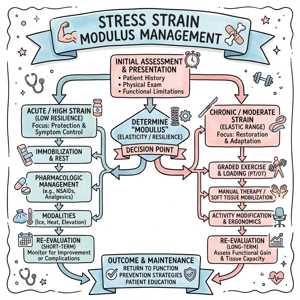
STRESS, STRAIN, AND ELASTIC MODULUS
Clinical summary
Fundamental Definitions
- •Stress (σ): Force / Area, units: Pa, MPa, GPa (N/m²)
- •Strain (ε): ΔL / L₀, dimensionless or %, relative deformation
- •Elastic modulus (E): σ / ε, stiffness, units: GPa
- •Hooke's law: σ = E × ε (elastic region only)
Elastic Modulus Values
- •Cobalt-chrome: 210-240 GPa (very stiff)
- •Stainless steel 316L: 200 GPa (stiff)
- •Titanium Ti-6Al-4V: 110 GPa (moderately stiff)
- •Cortical bone: 17 GPa (moderate)
- •PMMA cement: 2-3 GPa (low)
- •Cancellous bone: 0.1-1 GPa (very low)
- •Articular cartilage: 10 MPa = 0.01 GPa (very compliant)
Stress-Strain Curve Regions
- •1. Elastic: Linear, reversible, slope = E, follows Hooke's law
- •2. Yield: Transition to permanent deformation, 0.2% offset definition
- •3. Plastic: Permanent deformation, work hardening, strain increases faster
- •4. Ultimate tensile strength: Peak stress, maximum load capacity
- •5. Fracture: Complete failure, ductile (necking) vs brittle (sudden)
Ductile vs Brittle
- •Ductile: Large plastic deformation (greater than 5%), yields before fracture (warning)
- •Brittle: Minimal plastic deformation (less than 1%), sudden fracture (no warning)
- •Ductile fracture: Cup-and-cone, fibrous appearance
- •Brittle fracture: Flat, crystalline appearance
- •Clinical: Ductile preferred (safety), brittle avoided (catastrophic)
Key Concepts
- •Stiffness (E) and strength (σ_UTS) are independent properties
- •High E does not mean high strength (e.g., ceramics stiff but brittle)
- •Stress concentration: Local stress at notches/holes exceeds average stress
- •Stress concentration factor: Local stress / average stress (typically 3 for holes)
- •Explains crack initiation at screw holes in plates
Stress Shielding
- •Metal implant (110-240 GPa) much stiffer than bone (17 GPa)
- •Stiff implant carries majority of load for given deformation
- •Proximal bone experiences reduced stress
- •Wolff's law: Bone remodels to loading, reduced stress causes resorption
- •20-40% proximal bone loss common with stiff stems (Gruen zone 7)
- •Mitigation: Titanium (110 GPa), flexible design, porous proximal coating
Mechanical Testing
- •Tensile test: Dog-bone specimen, constant strain rate, plot σ vs ε
- •Compression test: Similar but compressive loading, specimen bulges
- •Four-point bending: For brittle materials, avoids gripping stress
- •Properties measured: E, σ_y, σ_UTS, ductility (% elongation)