Biomechanical Loads | Hip 3-7x BW | Free Body Diagrams | Arthroplasty Design
- Joint reaction force = resultant force acting across joint surface in response to external/internal loads
- Calculated using free body diagrams and static equilibrium (ΣF = 0, ΣM = 0)
- Hip: 3-7x body weight during normal gait, peak at mid-stance phase
- Abductor muscle force creates large hip reaction force (long moment arm from body weight)
- Clinical relevance: implant design, wear patterns, fixation requirements, bearing surfaces
- “Joint reaction force far exceeds body weight due to muscle forces and leverage
- “Free body diagram essential: isolate joint, show all forces (body weight, muscle, reaction)
- “Reducing moment arm reduces muscle force needed (reduces reaction force)
- “Hip offset restoration critical to maintain normal abductor biomechanics
- “Bearing surface wear directly related to magnitude of reaction force
Overview and Fundamental Concepts
Joint reaction force is the resultant force acting across a joint surface. It arises from the combined effect of external loads (body weight, ground reaction forces) and internal loads (muscle and ligament forces), and it is calculated from a free body diagram using static equilibrium, ΣF = 0 and ΣM = 0. Understanding it is fundamental to orthopaedic biomechanics, implant design and the pathophysiology of degenerative joint disease.
Why it exceeds body weight. Muscles attach close to joints, on short moment arms, while body weight acts at a distance from the joint through the centre of mass, on a long moment arm. To balance the moments about the joint the muscle force must be 2-4x body weight, and the joint reaction force is the vector sum of body weight plus that muscle force. That is why routine activities load a joint to several times body weight, and why any external load carried (bags, weights) adds to body weight and raises the joint force with it.
Why it matters. Joint reaction forces directly influence articular cartilage stress, bearing-surface wear in arthroplasty, fixation loads on implants, bone remodelling patterns and the progression of osteoarthritis. A surgeon has to understand them to optimise implant positioning, select appropriate bearing surfaces and counsel patients on activity modification.
How large. The forces vary systematically across joints and activities:
- Hip: 2.5-3x BW standing on one leg; 3-7x BW during normal gait, peaking at mid-stance; up to 8-10x BW during running or stumbling
- Knee: 2-3x BW walking; 3-4x BW stair climbing; 6-8x BW running; up to 24x BW landing from a jump (elite athletes)
- Ankle: 4-5x BW during normal walking; 8-13x BW during running, because of ground reaction force magnification
- Shoulder: 0.5-1.5x BW depending on arm position and load, the mechanics being different because the arm is non-weight-bearing
These magnitudes have been measured directly with instrumented implants and telemetry, which validated the theoretical calculations from biomechanical modelling.
The arthroplasty consequences run through the whole topic. Bearing surfaces must withstand millions of cycles at 3-7x body weight; volumetric wear in polyethylene is directly proportional to load; cement mantles and bone-implant interfaces experience the same cyclical loads; a malpositioned component alters the moment arms and raises the reaction force; and obesity and high-impact activity dramatically increase implant stress and failure risk.
Core Concepts - Biomechanical Calculation Principles
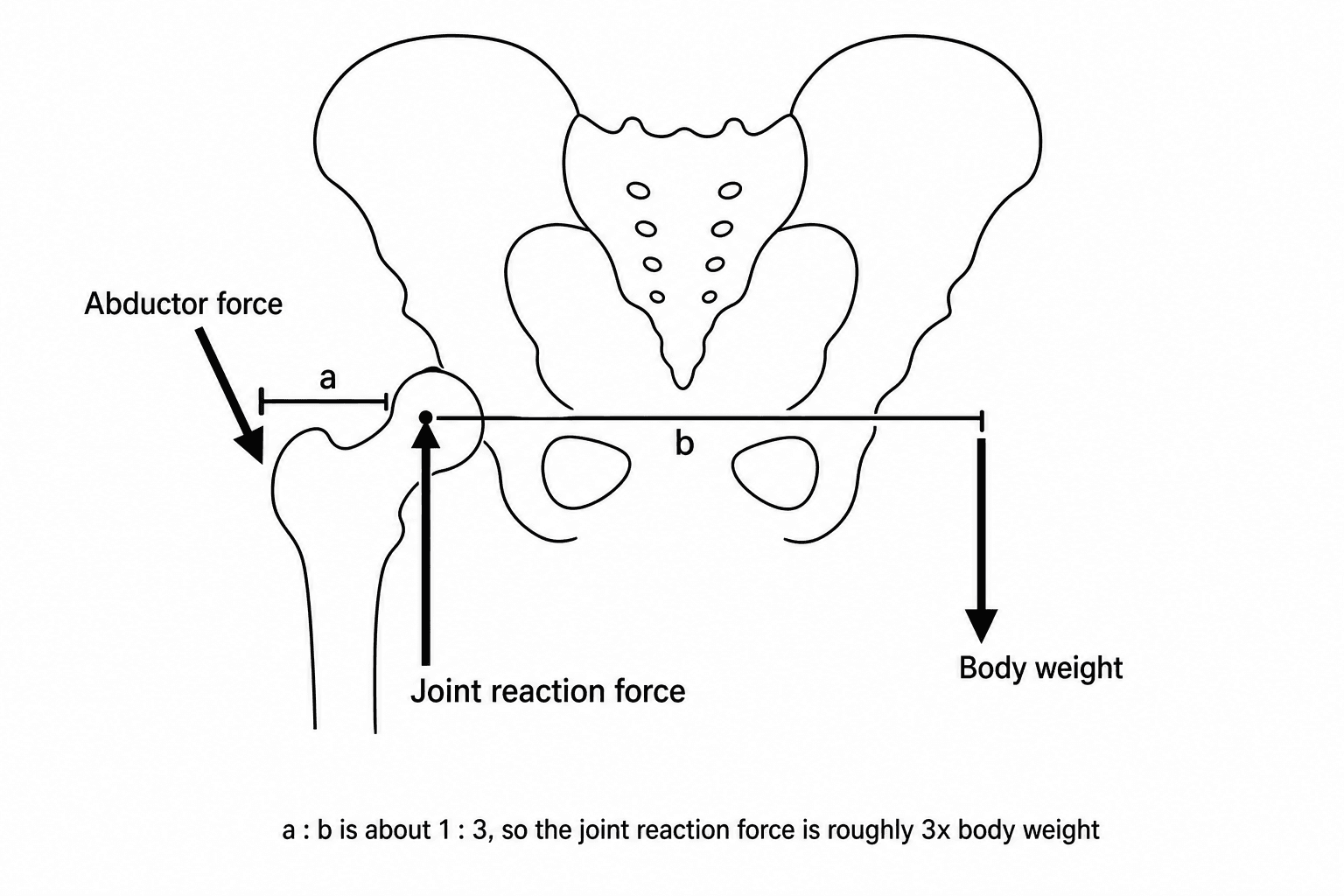
The free body diagram. The standard method applies static equilibrium to a free body diagram of the segment. The figure below is the hip version that every calculation in this topic reduces to.
The five steps. Work through them in this order every time:
- Isolate the segment. Draw the bone (the femur for a hip analysis) apart from its neighbours. The joint becomes a "cut" where the internal forces are exposed as unknowns.
- Identify all forces. Body weight (W) acting downward through the centre of mass; the muscle forces (Fm) of the primary stabilisers, the hip abductors here; and the joint reaction force (R), unknown in magnitude and direction, at the joint centre.
- Establish a coordinate system, typically horizontal (x) and vertical (y) axes aligned with the anatomical planes, and measure the moment arms, each the perpendicular distance from the line of a force to the pivot.
- Apply equilibrium. ΣFx = 0, ΣFy = 0 and ΣM = 0, the moments taken about any point.
- Solve. The moment equation gives the muscle force; the force equations then give the reaction force components; combine the components for the resultant magnitude and direction.
- Definition
- Total body mass × gravity
- Typical Hip Value
- 70 kg × 9.8 = 686 N
- Clinical Significance
- Baseline external load
- Definition
- Glut med/min contraction
- Typical Hip Value
- 2-3x body weight (1500 N)
- Clinical Significance
- Primary force magnitude
- Definition
- dW / dm (body weight / muscle)
- Typical Hip Value
- Typically 2.5:1
- Clinical Significance
- Mechanical disadvantage
- Definition
- Resultant across joint
- Typical Hip Value
- 3-7x BW (2500-5000 N)
- Clinical Significance
- Determines implant wear
Leverage. Muscles operate at a mechanical disadvantage. The moment arm of body weight about the hip is typically 10-15 cm, 2-3 times the abductor moment arm of 4-6 cm, so the abductors must generate 2-3 times body weight simply to balance the pelvis in single-leg stance.
Vector addition. The joint reaction force is not body weight minus muscle force. It is the vector sum of every force acting on the segment, and because muscle force and body weight act in roughly opposite directions vertically yet both compress the joint, the resultant exceeds either force on its own.
Static versus dynamic. The calculation above assumes static equilibrium, a patient standing still. During gait the acceleration terms add inertial forces (F = ma), which raise the peaks further at mid-stance and push-off.
Given: a 70 kg person standing on one leg, body weight moment arm 12 cm, abductor moment arm 5 cm. Find the hip reaction force.
Step 1: ΣM = 0 about the hip centre: Fm × 5 = W × 12, so Fm = 2.4W = 2.4 × 686 N = 1646 N.
Step 2: ΣFy = 0: R = Fm + W = 1646 + 686 = 2332 N = 3.4x body weight.
A favourite calculation question.
The free-body method is not limited to the limb joints tabulated in this topic. It applies equally to the lumbar spine, a favourite viva extension, which is governed by exactly the same short-lever-arm mechanics.
- Why disc loads are so high. The erector spinae act on a very short posterior lever arm, only about 5 to 6 cm behind the disc, whereas a held load and the weight of the trunk act on a long anterior lever arm. To balance the flexion moment about the L5-S1 disc the back extensors must generate a large force, and the disc compressive (reaction) force is the sum of that muscle force plus body and external load. It can reach several thousand newtons even when lifting modest weights, far exceeding the weight actually held.
- Keep the load close: it is moment-arm control. Bending forward or holding a load away from the body lengthens the anterior lever arm, multiplying the extensor force and the disc reaction force. Lifting with the load close to the trunk shortens that lever arm and is the single biggest reduction in spinal load, the biomechanical basis of safe-lifting advice, and why a "straight-back, load-close" technique protects the disc more than the leg-versus-back debate alone.
- Raised intra-abdominal pressure, the abdominal muscles bracing against the diaphragm, creates an anterior supporting column that slightly offloads the posterior elements, one rationale for bracing during heavy lifting.
Exam point: the lumbar disc obeys the same rule as the hip. A short erector-spinae lever arm against a long load lever arm makes L5-S1 compressive (reaction) forces reach several thousand newtons, so the most effective way to lower spinal load is to keep the load close to the body (shorten its moment arm), aided by raised intra-abdominal pressure.
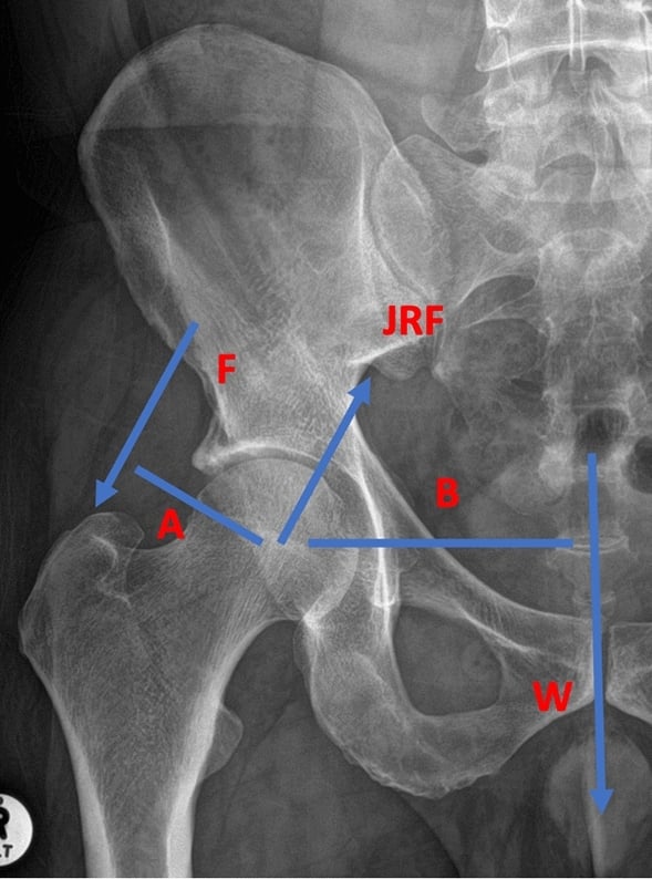
Hip Joint Reaction Forces
Through the gait cycle. The hip experiences some of the highest forces in the body, and the force changes phase by phase:
- Heel strike: 2-3x BW, initial loading
- Mid-stance: 4-7x BW, the peak, with single-leg support and rapid weight transfer
- Toe-off: 2-3x BW, the push-off phase
- Swing phase: under 1x BW, no ground contact
The double-peak pattern during stance reflects the two demands of single-leg support and forward propulsion.
The abductors. Gluteus medius and minimus run from the outer surface of the ilium to the greater trochanter and are the critical force generators at the hip: in single-leg stance they prevent the pelvis dropping on the opposite side. During mid-stance the pelvis and upper body, approximately 5/6 of total body weight, create a large overturning moment about the stance hip, and because the abductors act on a short moment arm, approximately 5-6 cm from the hip centre of rotation, they must generate 2-3x body weight to counter it.
Trendelenburg gait. When the abductors are weak or non-functional, after a superior gluteal nerve injury or with severe trochanteric pain syndrome, the patient cannot generate that abductor force. The pelvis drops on the swing side, and the patient compensates by lurching the trunk over the stance hip, which shortens the body-weight moment arm enough to maintain balance.
The differential of an abductor lurch. A positive Trendelenburg sign reflects a failure of the abductor force couple, but several distinct mechanisms produce it, each changing management, which is why it is a common viva probe.
- Mechanism (relation to joint reaction force)
- Abductor force generation lost; cannot balance body-weight moment
- Key Distinguishing Feature
- Weakness with intact tendon; iatrogenic after lateral/anterolateral approaches
- Management Direction
- Protect nerve intra-op; physiotherapy; usually recovers
- Mechanism (relation to joint reaction force)
- Mechanically uncoupled tendon; force not transmitted to trochanter
- Key Distinguishing Feature
- Lateral hip pain, MRI tendon discontinuity, fatty atrophy
- Management Direction
- Repair vs conservative depending on tear and demand
- Mechanism (relation to joint reaction force)
- Shortened abductor moment arm raises required muscle and reaction force
- Key Distinguishing Feature
- Radiographic short offset or low neck-shaft angle
- Management Direction
- Restore offset (THR templating; osteotomy)
- Mechanism (relation to joint reaction force)
- Voluntary off-loading to reduce reaction-force-driven pain
- Key Distinguishing Feature
- Pain-limited, improves with analgesia/aids
- Management Direction
- Treat OA; cane, weight loss, arthroplasty
- Mechanism (relation to joint reaction force)
- High, lateralised centre lengthens body-weight arm and concentrates contact stress
- Key Distinguishing Feature
- Shallow acetabulum, high centre on radiograph
- Management Direction
- Periacetabular osteotomy or reconstruction
- Mechanism (relation to joint reaction force)
- Altered abductor tension-length and pelvic obliquity
- Key Distinguishing Feature
- Measurable limb-length difference; corrects with block
- Management Direction
- Shoe raise; address surgical cause
Hip geometry. Several anatomical and surgical factors change the lever arms, and with them the reaction force:
- Biomechanical Effect
- Larger abductor moment arm
- Force Change
- Reduces force 10-20%
- Clinical Relevance
- Restore offset in THR for normal mechanics
- Biomechanical Effect
- Smaller abductor moment arm
- Force Change
- Increases force 15-30%
- Clinical Relevance
- Avoid excessive medialisation in THR
- Biomechanical Effect
- Shortens abductor moment arm
- Force Change
- Increases force
- Clinical Relevance
- May contribute to implant loosening
- Biomechanical Effect
- Reduces body weight moment
- Force Change
- Lowers abductor demand (Neumann; figures under Strategies below); an ipsilateral cane changed nothing
- Clinical Relevance
- Effective conservative measure
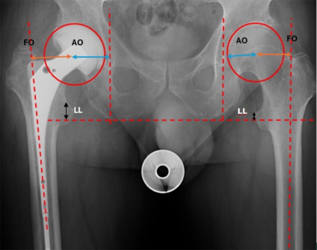
Femoral offset. In total hip replacement, maintaining or restoring normal femoral offset is biomechanically critical. Every 5 mm of offset lost raises the abductor force requirement by about 15%, and the reaction force and bearing-surface wear rise with it; restoring offset reverses that and improves abductor efficiency.
Limb length. Lengthening the limb tightens the abductors and improves their tension-length relationship, but if excessive it can increase the joint reaction force. Shortening reduces abductor tension and efficiency, and can produce a Trendelenburg gait.
What instrumented implants measured. Telemetry from instrumented hip replacements has validated the theoretical models. Bergmann and colleagues recorded peaks of 2.5-3.5x BW in normal walking in elderly patients with a THR; younger, more active patients generate up to 4-5x BW in normal gait; stumbling or a fall can produce transient peaks of 8-10x BW; and prolonged standing on one leg sustains 2.5-3x BW. These data set the implant design requirements and the wear-testing protocols: ISO standards require testing at 3x BW for 5-10 million cycles to simulate 10-20 years of use.
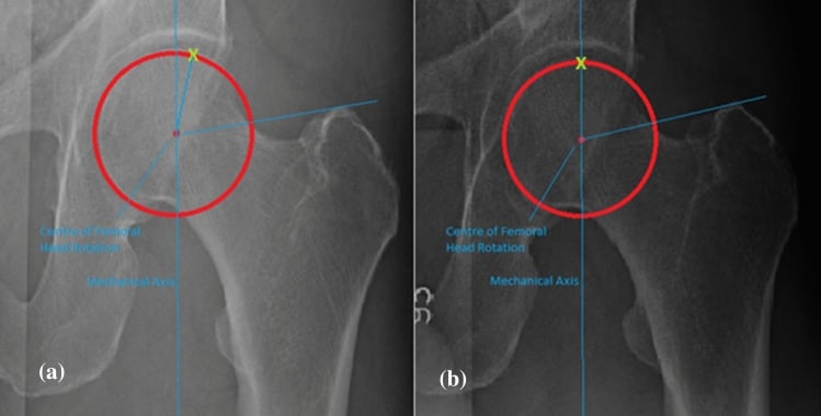
The free-body analysis above is essentially Pauwels' balance-beam (seesaw) model of the hip: the femoral head is the fulcrum, body weight acts on the long medial lever arm and the abductors pull on the short lateral lever arm, so the abductors must generate a large force and the resultant joint reaction force is several times body weight. This single concept generates two high-yield exam applications.
1. Reducing the reaction force by changing the lever arms. Anything that lengthens the abductor lever arm or shortens the body-weight lever arm lowers the required muscle force and therefore the reaction force. This is the principle behind increasing femoral offset, medialising the hip centre with the trunk (Pauwels), and a valgus or medial-displacement intertrochanteric osteotomy, used historically for OA and for difficult femoral-neck nonunions.
2. Pauwels classification of femoral neck fractures. The orientation of the fracture line relative to the horizontal determines how the joint reaction force is resolved across it:
- Pauwels I (about 30 degrees): the force is largely compressive across the fracture, favouring union.
- Pauwels II (about 50 degrees): intermediate.
- Pauwels III (about 70 degrees, near-vertical): the force becomes largely shear, which displaces the fracture and gives the highest nonunion and fixation-failure rate. The more vertical the fracture, the more a fixed-angle device (sliding hip screw or a fixed-angle plate) is favoured over parallel screws, and a valgus osteotomy can convert shear into compression.
Exam point: the hip is a Pauwels balance beam (fulcrum at the head, long body-weight arm against a short abductor arm); lengthening the abductor arm or shortening the body-weight arm lowers the reaction force, and a more vertical (Pauwels III) femoral neck fracture converts that large reaction force into shear, driving nonunion and changing the fixation choice.
Knee Joint Reaction Forces
Magnitude. Knee forces are lower than the hip's during walking but can exceed them in high-impact activity. Through the gait cycle:
- Heel strike: 2x BW, initial impact absorption
- Mid-stance: 2-3x BW, controlled flexion under eccentric quadriceps contraction
- Terminal stance: 2.5-3x BW, push-off preparation
- Swing phase: minimal, under 0.5x BW
On stairs the quadriceps work harder: 3-4x BW ascending, extending the knee against gravity, and 3-4.5x BW descending, under eccentric quadriceps control, which is often the higher of the two.
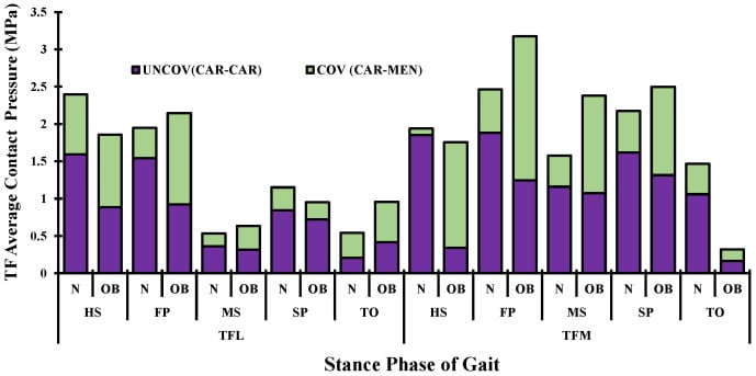
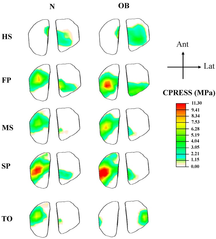
Two articulations. The tibiofemoral joint takes primarily compression from body weight and the ground reaction force, 2-4x BW during walking, distributed across the medial and lateral compartments in a 60:40 ratio favouring the medial side in normal alignment. The patellofemoral joint is loaded by the quadriceps and patellar tendons compressing the patella: its force equals the quadriceps force × sin(knee flexion angle / 2), peaks at 30-60 degrees of flexion (stair climbing, rising from a chair) and can reach 5-7x BW in deep knee bends or squatting. The different force patterns are why patellofemoral and tibiofemoral arthritis present differently, patellofemoral pain on stairs and tibiofemoral pain on walking.
The quadriceps. The quadriceps group is the primary force generator at the knee, and during gait it must do three things:
- Absorb impact in early stance (eccentric contraction)
- Stabilise the knee in mid-stance (isometric contraction)
- Extend the knee for push-off (concentric contraction in terminal stance)
The quadriceps force can be 3-4x body weight in these activities, and it contributes to the total knee reaction force through the patellar mechanism. Standing from a chair at 60 degrees of knee flexion is the worked example: quadriceps force approximately 4x BW; patellar contact force Fq × sin(60°/2) ≈ 4 × 0.5 = 2x BW; tibiofemoral compression 3-4x BW, the vector sum of the forces.
Alignment. Coronal alignment decides how the tibiofemoral load divides between the compartments:
- Mechanical Axis
- Through knee centre
- Medial Compartment Force
- 60% of total force
- Lateral Compartment Force
- 40% of total force
- Mechanical Axis
- Medial to knee centre
- Medial Compartment Force
- 70-90% of total force
- Lateral Compartment Force
- 10-30% of total force
- Mechanical Axis
- Lateral to knee centre
- Medial Compartment Force
- 30-40% of total force
- Lateral Compartment Force
- 60-70% of total force
- Mechanical Axis
- Through prosthesis centre
- Medial Compartment Force
- Equal distribution
- Lateral Compartment Force
- Equal distribution
Varus malalignment overloads the medial compartment and accelerates medial osteoarthritis, and the unloading of the lateral compartment in a varus knee leads to medial bone loss and progression of the deformity. Total knee replacement therefore aims to restore neutral alignment for equal load distribution, and a high tibial osteotomy shifts the mechanical axis laterally to unload the diseased medial compartment.

Shoulder Joint Reaction Forces
What is different. The shoulder is non-weight-bearing: the arm weighs approximately 5% of body weight, far less than the loads on the lower limb, and the forces depend heavily on arm position and on any external load carried. The shallow glenoid prioritises range of motion over stability, so the head is suspended by muscle, the rotator cuff and deltoid balancing their forces to keep it centred.
The force couple. The deltoid elevates the arm in abduction with a superiorly directed force, 2-3x arm weight during abduction, that tends to pull the humeral head upward into the acromion. The rotator cuff (subscapularis, supraspinatus, infraspinatus, teres minor) pulls medially and inferiorly at 1.5-2x arm weight, compressing the head and countering the deltoid, and its net effect is to compress and centre the head on the glenoid. Together they form a force couple that allows smooth elevation while keeping the glenohumeral joint stable; a rotator cuff tear disrupts the balance and allows superior migration of the head, superior escape.
At 90 degrees of abduction. For a 70 kg person the arm weighs 5% BW, about 35 N. The deltoid produces approximately 800-1000 N to overcome the arm-weight moment, the rotator cuff approximately 600-800 N to balance the deltoid, and the glenohumeral reaction force comes to 1-1.5x body weight (700-1000 N). That is far below the hip or knee because the arm weight is small, but carrying an external load (groceries, tools, weights) dramatically increases it, potentially to 2-3x body weight.
Reverse shoulder arthroplasty. The reverse design alters the normal biomechanics to compensate for a deficient rotator cuff:
- Medialised centre of rotation: lengthens the deltoid moment arm, reducing the force needed
- Distal and lateral offset: increases the deltoid moment arm and pretensions the deltoid for more efficient force generation
- Reaction force: the contact force can increase, but it is distributed over the larger glenosphere surface
- Net effect: the deltoid can elevate the arm without a functional rotator cuff
Glenoid wear. In anatomic shoulder replacement posterior glenoid wear is common. It arises from the tendency of the osteoarthritic shoulder to posterior subluxation and from eccentric loading with the force concentrated posteriorly, which puts a greater reaction force on a smaller contact area. Left uncorrected it risks component loosening, which is what posterior augmented glenoid components address.
Clinical Implications for Arthroplasty
Wear. Polyethylene wear is directly proportional to the joint reaction force. Archard's law states it: volumetric wear ∝ (contact force × sliding distance) / material hardness. Doubling body weight approximately doubles the wear rate in THA; high-impact activities such as running and jumping, at 6-10x BW, cause disproportionate wear; obesity is a major risk factor for accelerated polyethylene wear and osteolysis; and the debris leads to osteolysis, aseptic loosening and revision surgery.
- Effect on Reaction Force
- Increases force proportionally
- Effect on Wear
- Linear increase in wear
- Clinical Action
- Weight loss before surgery; consider hard bearings
- Effect on Reaction Force
- Forces 6-10x BW
- Effect on Wear
- Exponential increase
- Clinical Action
- Activity modification; avoid polyethylene if young/active
- Effect on Reaction Force
- Lengthens the abductor arm
- Effect on Wear
- Reduced wear rate
- Clinical Action
- Template carefully; prioritise offset in THR
- Effect on Reaction Force
- Reduces abductor demand
- Effect on Wear
- Significant wear reduction
- Clinical Action
- Recommend during high-wear period (first 2 years)
Cemented fixation. The cement mantle must withstand the shear and compressive stresses of cyclical loading, and high reaction forces increase cement stress and creep, the time-dependent deformation. An adequate mantle of 2-4 mm distributes the stress; thin mantles crack. Modern cementing technique emphasises pressurisation to improve bone-cement interdigitation.
Uncemented fixation. The initial press-fit must resist motion under cyclical load until osseointegration occurs. Micromotion greater than 150 microns prevents bone ingrowth and causes fibrous encapsulation, and a high reaction force can exceed the friction force at the interface, causing early migration and failure. Porous coatings and surface treatments (hydroxyapatite, trabecular metal) promote osseointegration.
Stress shielding. A stiff implant such as a cobalt-chrome stem carries more of the load than the surrounding bone because of the elastic modulus mismatch. Bone stress falls below the threshold for remodelling (Wolff's law) and the proximal bone resorbs; the magnitude of the joint reaction force influences how far this goes.
Component positioning. Surgical technique sets the postoperative joint reaction force, and the levers differ by joint.
Total hip replacement:
- Femoral offset: use a stem of appropriate offset, and consider a high-offset stem for a large patient; the 5 mm-for-15% relationship above is the reason
- Limb length: match the contralateral side; excessive lengthening increases abductor force and excessive shortening reduces abductor efficiency
- Cup position: excessive medialisation reduces offset and increases the reaction force, so keep the centre of rotation near its anatomic position
- Anteversion: incorrect version alters the force direction, causing edge loading and accelerated wear
- Bearing: consider a hard bearing, ceramic or metal, for a young, high-demand patient, to resist wear under high forces
Total knee replacement:
- Alignment: a neutral mechanical axis through the knee centre gives equal medial and lateral force distribution
- Joint line: lowering it by over-resecting the distal femur alters patellar height and increases patellofemoral forces
- Rotation: internal rotation of the femoral or tibial component alters patellar tracking and patellofemoral forces
- Slope: posterior tibial slope affects anteroposterior stability and the quadriceps force required
- Constraint: higher forces may require a more constrained design (PS versus CR)
Total shoulder replacement:
- Glenoid version: retroversion increases the posterior eccentric force and accelerates wear, so correct it to avoid posterior glenoid wear
- Humeral offset: affects the deltoid and rotator cuff lever arms and so the force each must produce
- Reverse for cuff deficiency: alters the biomechanics to reduce the deltoid force requirement
- Reverse lateralisation: the optimal lateralisation balances deltoid efficiency against the reaction force magnitude and glenoid stress
Strategies to Reduce Joint Reaction Forces
Weight. Peak hip force is 238-260% of body weight in walking and stair climbing on the in vivo data in the evidence section, so every 1 kg of body weight lost removes roughly 2.4-2.6 kg from the peak hip load during gait, and roughly 2.6-3.5 kg from the peak at the knee, scaling up in more demanding activities. For an obese patient losing 10 kg that is roughly 24-26 kg off the peak hip load, more during higher-demand activity, repeated over millions of loading cycles for years, with a proportional fall in the polyethylene wear rate. Weight loss is the single most effective intervention for force reduction.
Activity. The peak force of an activity decides whether it is encouraged after arthroplasty:
- Peak Force
- 3-5x BW
- Recommendation Post-THA/TKA
- Encouraged, no limit
- Rationale
- Low impact, good for cardiovascular health
- Peak Force
- 1-2x BW
- Recommendation Post-THA/TKA
- Excellent option
- Rationale
- Low force, good ROM exercise
- Peak Force
- Minimal force
- Recommendation Post-THA/TKA
- Ideal exercise
- Rationale
- No impact, full body workout
- Peak Force
- 2-4x BW
- Recommendation Post-THA/TKA
- Acceptable with technique
- Rationale
- Moderate force, avoid twisting
- Peak Force
- 6-10x BW
- Recommendation Post-THA/TKA
- Not recommended
- Rationale
- High impact increases wear and loosening risk
- Peak Force
- 10x+ BW
- Recommendation Post-THA/TKA
- Contraindicated
- Rationale
- Extreme forces, high revision risk
The contralateral cane. A cane in the opposite hand creates an upward force on the far side of the body, reducing the body-weight moment about the stance hip. Neumann measured the effect as abductor EMG in patients with hip prostheses: abductor demand fell by 31% in normal use and by 42% with a near-maximal push, and the joint reaction force falls broadly in proportion, by 20-30%, because muscle force is its dominant component. An ipsilateral cane changed abductor activity not at all in the same study, so the side is not a refinement, it is the whole effect. The technique is a cane in the hand opposite the affected hip, advanced together with the affected leg.
The walker. Bilateral support distributes weight across all four points and so reduces the force on each hip and knee. It is particularly effective in the early postoperative period while bone ingrowth is occurring; the cost is a slower gait, less efficient than a cane for long-term use.
Shoes. Cushioned soles with shock absorption reduce the impact force at heel strike, and rocker-bottom soles reduce ankle and midfoot forces by smoothing the push-off transition. The effect is modest, a 5-10% force reduction, but may benefit marginal cases.
Surgery. The surgical levers are the positioning decisions set out under component positioning above: offset, cup position and limb length at the hip; alignment, joint line, rotation and constraint at the knee; version and lateralisation at the shoulder.
Management Algorithm
Guidelines, Registries & Global Practice
Global Epidemiology
Joint reaction forces are the mechanical driver behind load-related cartilage degeneration, so the global burden of osteoarthritis (OA) frames their clinical importance. The Global Burden of Disease 2019 analysis reports age-standardised prevalence per 100,000 of approximately 4376 for knee OA, 1726 for hand OA and 401 for hip OA, with hip and knee OA prevalence rising significantly between 1990 and 2019 (Li XX et al., Int J Rheum Dis 2024 DOI). High body-mass is a leading modifiable contributor: increased body weight raises every lower-limb joint reaction force in direct proportion, accelerating OA and, after arthroplasty, bearing wear. Obesity prevalence is high in many high-income countries (around 30% of adults), magnifying joint loading at a population level.
Guideline Positions (Side by Side)
There is no joint-reaction-force-specific guideline; the principles are operationalised within OA management and arthroplasty optimisation guidance. The table summarises how major bodies translate the underlying biomechanics into practice.
- Relevant Guidance
- Management of OA of the hip and knee
- Stance on Load Reduction
- Strongly recommends weight loss and low-impact exercise to reduce joint loading; supports patient-specific activity counselling
- Evidence Level
- Moderate-strong
- Relevant Guidance
- Osteoarthritis: assessment and management (NG226)
- Stance on Load Reduction
- Therapeutic exercise and weight management are core first-line; offers arthroplasty when conservative load-modifying measures are insufficient
- Evidence Level
- Moderate
- Relevant Guidance
- Best-practice arthroplasty standards
- Stance on Load Reduction
- Emphasise restoring offset, leg length and alignment to normalise muscle and joint reaction forces
- Evidence Level
- Consensus
- Relevant Guidance
- Consensus on hip and knee biomechanics
- Stance on Load Reduction
- Endorse biomechanical optimisation (offset, alignment) and pre-operative risk-factor modification
- Evidence Level
- Consensus
- Relevant Guidance
- Hip and knee wear-simulator standards
- Stance on Load Reduction
- Codify in vivo telemetry force profiles (Bergmann, Kutzner) into mandatory implant testing
- Evidence Level
- Standard
Registry Evidence
National arthroplasty registries provide the largest real-world signal that joint loading governs implant survival. An Australian-led meta-analysis of more than 3.1 million total knee arthroplasties found higher all-cause revision (OR 1.15) and deep infection (OR 1.47) in obese patients (Onggo JR et al., ANZ J Surg 2021 DOI). Registry observations consistent with force principles include:
- AOANJRR (Australia): higher cumulative revision in high-BMI patients and in younger, higher-demand recipients, and better survivorship when normal biomechanics (offset, alignment) are restored.
- NJR (England, Wales, NI) and AJRR (USA): report increased early revision for instability and loosening with malposition, the mechanism of which is altered moment arms and reaction-force direction.
- Bearing-surface trends (hard-on-hard or highly cross-linked polyethylene for young, active patients) reflect the force-wear relationship (Archard's law).
Practice Variation and Controversies
- Mechanical versus kinematic alignment in TKA: instrumented-implant data (Kutzner et al., Bone Joint J 2017) show varus malalignment raises the medial force ratio, fuelling debate over how much constitutional varus is safe to leave.
- BMI thresholds for elective arthroplasty: some systems apply hard BMI cut-offs while others reject them as inequitable; evidence for force-driven complications informs but does not settle this.
- Offset targeting: increasing femoral offset reduces abductor and reaction force but risks trochanteric pain and leg-length issues, so targets vary between centres.
Pre-operative and Conservative Optimisation
- Pre-operative weight optimisation and dietitian input are increasingly embedded in arthroplasty pathways internationally to lower joint reaction forces before surgery.
- Physiotherapy-led gait retraining and contralateral cane education reduce hip joint reaction force conservatively.
- Multimodal analgesia supports the activity modification and load-reduction programmes that underpin conservative OA care before arthroplasty.
MCQ Practice Points
Q: What is the hip joint reaction force during single-leg stance and why is it so high?
A: Approximately 2.5-3× body weight. High because of mechanical disadvantage: Body weight (minus stance leg ~55 kg for 70 kg person) acts through moment arm ~10-12 cm from hip. Abductors have moment arm only ~5 cm. To balance, abductors must generate ~2× BW force. Joint reaction force = vector sum of body weight + abductor force, directed superolaterally. During walking, peak force reaches 3-7× BW.
Q: Compare the joint reaction forces at the hip, knee, and ankle during normal gait.
A: Hip: 3-7× BW walking, up to 10× BW stumbling. Knee: 2-3× BW walking, 3-4× stairs, 6-8× running. Ankle: 4-5× BW walking, 8-13× BW running - highest forces in lower limb. Ankle forces are highest due to long lever arm of forefoot and short Achilles moment arm. These values guide implant design and fixation strength requirements.
Q: How does using a walking stick in the opposite hand reduce hip joint reaction force?
A: A walking stick on the contralateral side creates an external moment that assists the hip abductors. Using only 10-15% of body weight through the stick can reduce hip joint reaction force by 20-30%. The stick effectively reduces the moment arm of body weight that abductors must counter. This is why osteoarthritis patients intuitively use a stick on the opposite side.
Q: What forces act on the knee joint during stair climbing?
A: 3-4× body weight. Higher than level walking because: 1) Greater knee flexion angle increases patellofemoral forces, 2) Quadriceps must generate high force to extend knee against gravity, 3) Body weight acts through longer moment arm in flexion. Patellofemoral joint force during stair descent can reach 7-8× BW. Clinical relevance: early symptom in patellofemoral OA, TKA rehabilitation.
Q: How does contact area affect contact stress in the hip joint?
A: Contact stress = Force / Contact area. In the normal hip, joint reaction force is distributed over 70-80% of available articular surface area. In hip dysplasia, reduced coverage concentrates force over smaller area, dramatically increasing contact stress and accelerating cartilage damage. Periacetabular osteotomy increases coverage area, reduces peak contact stress, and delays or prevents OA.
Exam Viva Scenarios
Practise clinical reasoning and management decisions out loud
“A 70 kg patient is standing on one leg. The moment arm of body weight about the hip joint center is 12 cm. The moment arm of the hip abductor muscles is 5 cm. Calculate the hip abductor muscle force and the total hip joint reaction force. Assume static equilibrium and forces acting in vertical plane only.”
“You are planning a total hip replacement in a 45-year-old male tradesman, 95 kg, BMI 32, who wishes to return to physically demanding work involving repetitive lifting and carrying. Discuss how joint reaction forces influence your choice of bearing surface and surgical technique.”
“An examiner asks you to explain the biomechanical principle of how a contralateral cane reduces hip joint reaction forces. Draw a free body diagram and explain the mechanism.”
Core Definitions
- Joint reaction force = resultant force across joint surface from external + internal loads
- Calculated using free body diagrams and equilibrium (ΣF=0, ΣM=0)
- Magnitude FAR EXCEEDS body weight due to muscle forces and leverage
- Primary clinical relevance: implant wear, fixation loads, component design
Force Magnitudes (Multiples of Body Weight)
- Hip: 2.5x BW standing one leg; 3-7x BW normal gait; 8-10x BW stumbling
- Knee: 2-3x BW walking; 3-4x BW stairs; 6-8x BW running; 24x BW jump landing
- Ankle: 4-5x BW walking; 8-13x BW running (higher than hip/knee!)
- Shoulder: 0.5-1.5x BW (non-weight-bearing, lower forces)
Hip Biomechanics - Essential Facts
- Abductor muscles (glut med/min) prevent pelvic drop during single-leg stance
- Abductor moment arm ~5 cm; body weight moment arm ~12 cm (2.5:1 ratio)
- Mechanical disadvantage requires abductor force = 2-3x body weight
- Hip reaction = abductor force + body weight = 3-4x BW static, 3-7x BW gait
- Peak force at mid-stance phase of gait cycle (single leg support)
Free Body Diagram Calculation Steps
- 1. Isolate segment; draw all forces (W, Fm, R)
- 2. Define coordinate system and measure moment arms
- 3. ΣM=0 about joint: Solve for muscle force Fm
- 4. ΣF=0: Solve for reaction force R (R = Fm + W for vertical)
- 5. Combine components if 2D/3D to get resultant magnitude
Factors Increasing Reaction Forces
- Obesity (proportional increase - each 1 kg of body weight adds ~2.4-2.6 kg to peak hip force)
- High-impact activities (running 6-8x BW, jumping 10-24x BW)
- Reduced offset/moment arm (medialized cup, coxa vara)
- External loads carried (groceries, tools, weights)
- Malalignment (varus knee overloads medial compartment)
Reducing Forces Clinically
- Weight loss (single most effective: 1 kg lost removes ~2.4-2.6 kg at the hip, ~2.6-3.5 kg at the knee)
- Contralateral cane (~31% reduction in abductor demand, 42% with a firm push; ipsilateral does nothing)
- Activity modification (walk vs run; avoid impact sports post-arthroplasty)
- Surgical optimization: restore offset, maintain alignment, optimize biomechanics
- Assistive devices (walker, cane, shoe cushioning)
THR/TKR Biomechanical Principles
- Restore femoral offset: 5 mm reduction increases force 15%, accelerates wear
- Neutral alignment TKR: equal medial/lateral distribution prevents overload
- Bearing surface selection: hard bearings (ceramic) for high forces/young patients
- Component position affects moment arms and force distribution
- Wear proportional to force (Archard's law): High forces = high wear rate
Exam Mnemonics
- Hip forces: 3-7 BW gait (remember 'three to seven steps')
Viva Traps to Avoid
- Stating R = Fm - W (WRONG! R = Fm + W, both compress joint)
- Forgetting to convert kg to Newtons (× 9.8 m/s²)
- Ipsilateral cane reduces force (NO! Must be contralateral)
- Joint force equals body weight (NO! Forces are multiples of BW)
- Not drawing free body diagram when asked by examiner
Evidence Base and Key Studies
Bergmann Hip Contact Force Telemetry (Landmark In Vivo Dataset)
- Direct in vivo measurement of hip contact forces using instrumented femoral implants with telemetry in four patients during activities of daily living
- Average peak hip contact force walking at about 4 km/h: 238% body weight
- Stair ascent 251% BW; stair descent 260% BW (descent exceeds ascent)
- Implant torsion about the stem axis is approximately 23% greater on stair ascent than level walking, a key driver of stem fixation failure
Kutzner In Vivo Tibiofemoral Loading (Landmark Knee Dataset)
- Instrumented TKA with telemetry measured tibiofemoral contact forces in five subjects during activities of daily living
- Peak resultant force highest on stair descent (346% BW), then stair ascent (316% BW) and level walking (261% BW)
- Resultant force acted almost vertically on the tibial plateau even in high flexion; shear forces were 10-20 times smaller than the axial force
- In vivo dynamic forces were generally lower than predicted by many mathematical models, but exceeded several existing implant test standards
Kutzner: Coronal Alignment Drives Mediolateral Force Distribution
- Instrumented TKA in nine patients with full-leg coronal radiographs
- Medial force ratio correlated strongly with tibiofemoral alignment in one-legged stance (R-squared 0.88) and dynamic single-limb loading (R-squared 0.59)
- Varus malalignment increased the medial force ratio to as much as 88% of total load
- Force shifted laterally during double-limb support and higher flexion angles
Obesity, Joint Loading and Arthroplasty Outcomes (Large Meta-Analysis)
- Meta-analysis of 91 studies and over 3.1 million total knee arthroplasties (Australian-led, AOANJRR-linked authors)
- Obese patients (BMI 30 or more) had higher all-cause revision risk (OR 1.15, 95% CI 1.08-1.24)
- Deep infection risk increased (OR 1.47); morbid obesity (BMI 40 or more) raised deep infection risk further (OR 1.98)
- Higher rates of complications, readmission and wound problems, consistent with elevated mechanical joint loading plus metabolic risk
Asayama: Reconstructed Hip Geometry and Abductor Strength after THA
- 60 limbs in 30 unilateral THA patients with a normal contralateral hip compared radiographically and by dynamometry
- The ratio of femoral offset to the body-weight lever arm correlated positively with abductor strength ratio (r 0.49, p 0.006)
- The ratio of hip-centre height to pelvic height correlated negatively with strength (r -0.57, p 0.001)
- Slightly increased offset with restoration of a normal, slightly inferomedial hip centre optimised abductor function
Neumann: Contralateral Cane Reduces Hip Abductor Demand
- Randomised crossover EMG study of 24 subjects with a unilateral hip prosthesis
- Cane held contralateral to the prosthesis reduced hip abductor EMG activity by 31% versus walking with no cane
- Near-maximal contralateral cane effort reduced abductor activity by 42%
- An ipsilateral cane produced no significant reduction, confirming the cane must be on the opposite side
Bergmann: First In Vivo Glenohumeral Contact Forces
- First worldwide in vivo measurement of glenohumeral contact force using an instrumented shoulder implant with telemetry
- Contact force remained below 100% body weight for most activities of daily living
- Force rose to about 130% BW near the limits of motion or against external resistance
- Peak of about 150% BW occurred when turning a blocked steering wheel with maximal effort
Global Burden of Osteoarthritis (GBD 2019)
- GBD 2019 age-standardised prevalence per 100,000: knee OA 4376, hand OA 1726, hip OA 401
- Hip and knee OA prevalence rose significantly from 1990 to 2019 (hip AAPC +0.43%, knee +0.17%)
- Europe and the Americas carry the highest hip OA burden; Asia has a high knee OA burden
- High body-mass is a leading modifiable contributor to OA disability worldwide